Topology structure of intensive direct current ice-melting device for wind farm

A technology of DC ice melting and topology structure, which is applied in circuit devices, wind power generation, cable installation, etc., can solve the problems of large differences in power collection lines of wind farms, small capacity of agricultural network ice melting devices, and large floor space. , to meet the requirements of line ice melting capacity, large-scale current regulation capability, and small footprint

Active Publication Date: 2018-12-18
STATE GRID HUNAN ELECTRIC POWER +2
View PDF7 Cites 0 Cited by
  • Summary
  • Abstract
  • Description
  • Claims
  • Application Information

AI Technical Summary

Problems solved by technology

[0003] In order to improve the ability of transmission lines to resist ice disasters, many domestic units have developed various types of DC ice-melting devices, which provide a solid technical guarantee for the safe and stable operation of the power grid in winter. However, the existing ice-melting devices are mainly for the main grid or agricultural Grid transmission lines are not suitable for wind farm transmission lines to melt ice. The existing ice melting devices mainly have the following problems: Problem 1. The line shape of the ice melting line is relatively uniform or close, while the line shape of the wind farm power collection line and the sending line The difference is large, which puts forward higher requirements for the large-scale current regulation ability of the ice melting device; problem 2, the capacity of the ice melting device of the main grid is too large, while the capacity of the ice melting device of the rural grid is too small, which cannot meet the ice melting of the transmission line of the wind farm demand; problem 3, the construction area of ​​existing ice-melting devices is relatively large, and wind farms generally occupy a small area, which is difficult to meet the land demand for the construction of existing ice-melting devices; problem 4, the construction cost of existing ice-melting devices is relatively high , it is difficult to popularize and apply in wind farms as power generation enterprises

Method used


Image

  • Topology structure of intensive direct current ice-melting device for wind farm
  • Topology structure of intensive direct current ice-melting device for wind farm
  • Topology structure of intensive direct current ice-melting device for wind farm

Examples


Embodiment Construction

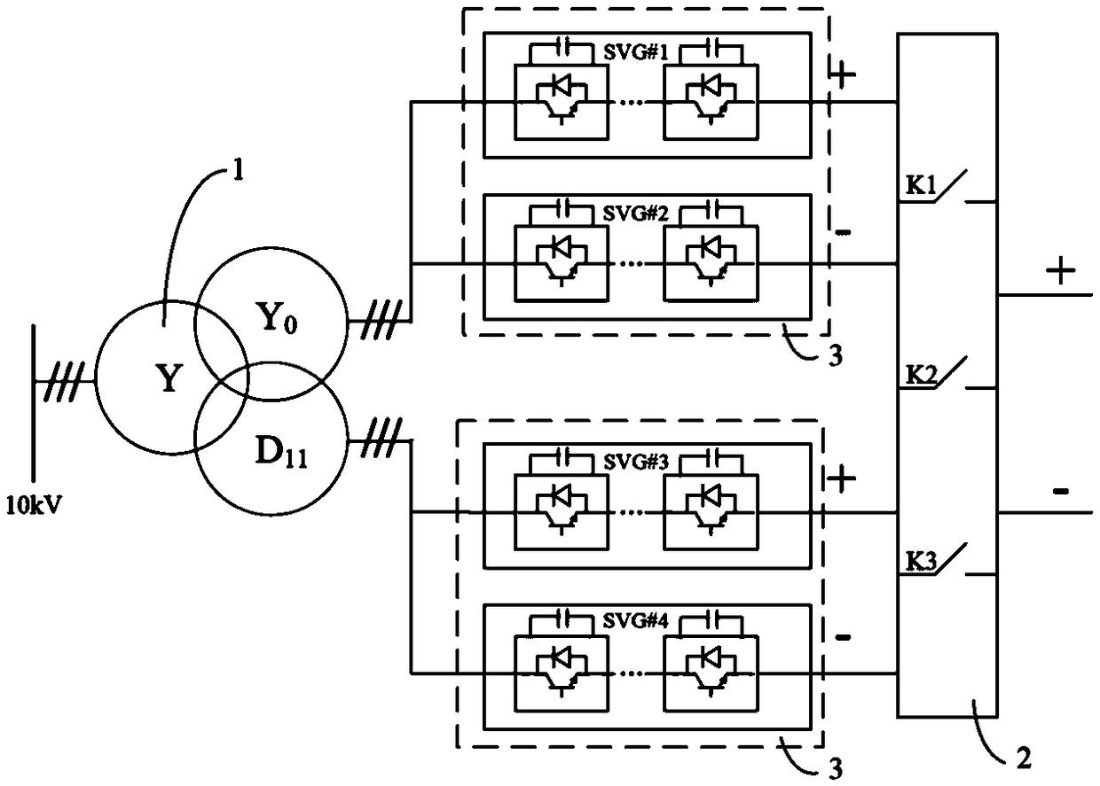
[0019] Such as figure 1 As shown, the topological structure of the intensive DC ice-melting device for wind farms in this embodiment includes a three-winding ice-melting transformer 1, a series-parallel switch 2 and two sets of dynamic reactive power compensation units 3, and three windings of the three-winding ice-melting transformer 1 Including the primary winding and two secondary windings, the dynamic reactive power compensation unit 3 includes two SVGs (dynamic reactive power compensation devices) arranged in parallel, the primary winding of the ice-melting transformer 1 is connected to the power grid, and the secondary windings are respectively connected to different The two SVGs of the dynamic reactive power compensation unit 3 are connected, the output ends of each SVG are respectively connected to the input ends of the series-parallel switch 2, and the output ends of the series-parallel switch 2 are connected to the line to be deiced. Functionally, this embodiment ca...


PUM


Abstract

The invention discloses a topological structure of an intensive DC ice-melting device for a wind farm, which includes a three-winding ice-melting transformer, a series-parallel knife switch and two sets of dynamic reactive power compensation units. The three windings of the three-winding ice-melting transformer include primary side windings and two secondary windings, the dynamic reactive power compensation unit includes two SVGs arranged in parallel, the primary winding of the ice-melting transformer is connected to the power grid, and the secondary winding is connected to two SVGs of different dynamic reactive power compensation units, each SVG The output terminals of the series and parallel knife switches are respectively connected to the input terminals of the series and parallel knife switches, and the output ends of the series and parallel knife switches are connected to the lines to be melted. The invention can realize the multifunctional output of the standard dynamic reactive power compensation device SVG of the wind farm, which is usually used for voltage reactive power compensation of the wind farm power grid, and used for melting ice when the lines of the wind farm are covered with ice in winter, and has a wide range of current adjustment capabilities to meet There are large differences in line types and the ice melting requirements of different lines can meet the ice melting capacity requirements of wind farm lines, and the land occupation is small and the construction cost is low.

Description

technical field [0001] The invention relates to electrical engineering technology, in particular to a topological structure of an intensive DC ice-melting device for a wind farm. Background technique [0002] In recent years, under the dual pressure of rapid increase in energy consumption, rising prices and deterioration of the global ecological environment, countries all over the world have placed an important position on the development and utilization of renewable new energy. Among many renewable energy sources, wind energy is favored by people for its great advantages and development potential. Wind power generation is also developing rapidly and has become an industry with strong vitality. my country is very rich in wind energy resources. Using the wind speed at a height of 10 meters to calculate, the theoretical reserves of land wind energy resources are 3.226 billion kilowatts, and the actual exploitable resources are 253 million kilowatts. The construction of wind fa...

Claims


Application Information

Patent Timeline
Patent Type & Authority Patents(China)
IPC IPC(8): H02G7/16H02J3/18H01F30/04
CPCH01F30/04H02G7/16H02J3/1857Y02E10/76Y02E40/10
Inventor 陆佳政朱思国李波谭艳军黄清军朱远
Owner STATE GRID HUNAN ELECTRIC POWER
Why Eureka
Try Eureka