Optimal output optimization method of hydraulic power plant set

A technology of optimal output and optimization method, applied in the direction of single-grid parallel feeding arrangement, etc., can solve the problem of inability to visually observe the allowable output standard of the water head of the unit, and achieve the effect of optimal scheduling

A technology of optimal output and optimization method, applied in the direction of single-grid parallel feeding arrangement, etc., can solve the problem of inability to visually observe the allowable output standard of the water head of the unit, and achieve the effect of optimal scheduling

CN107196346AInactive Publication Date: 2017-09-22NANJING HEHAI NANZI HYDROPOWER AUTOMATION +3

Image

  • Optimal output optimization method of hydraulic power plant set
  • Optimal output optimization method of hydraulic power plant set
  • Optimal output optimization method of hydraulic power plant set

Examples


Embodiment Construction

[0026] The present invention will be further described below in conjunction with the accompanying drawings. The following examples are only used to illustrate the technical solution of the present invention more clearly, but not to limit the protection scope of the present invention.

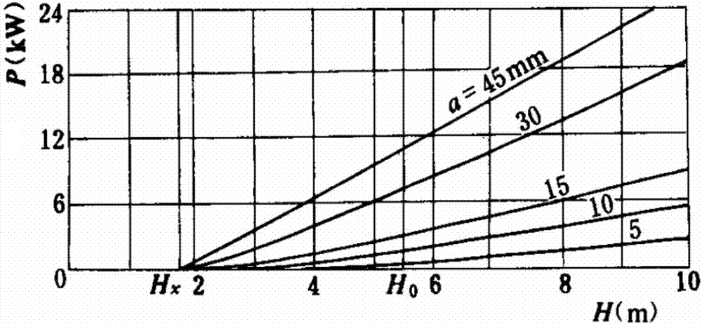
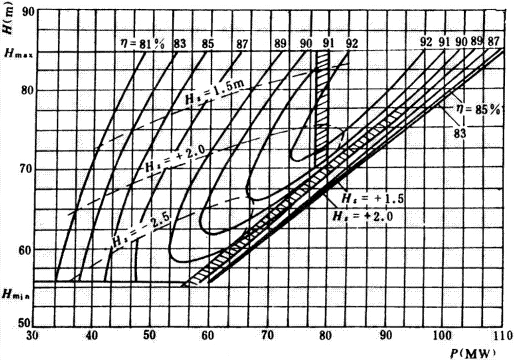
[0027] The water head characteristic curve of the unit is the relationship curve between the output of the unit and the water head, such as figure 1 As shown, according to the water head characteristic curve of the unit, it can be seen that the output of the unit is positively correlated with the water head, and the curves under each guide vane opening are drawn from the corresponding no-load head point, which is an approximate linear relationship. The larger the guide vane opening, the steeper the straight line is. Combined with the comprehensive characteristic curve of unit operation, such as figure 2 As shown, when the water head is high, the output of the unit is large, and the output is l...


PUM


Abstract

The invention discloses an optimization method for the optimum output of a hydropower plant unit, which is obtained based on the research on the standard output curve of the hydropower plant. Taking the standard output curve of the current water head unit as the reference standard for unit load adjustment, the current unit output status can be visually observed, and the unit output can be adjusted in real time to make it reach the best state, which provides a basis for unit optimization scheduling, cost reduction and efficiency increase, and can As a production management index of unit output efficiency.

Description

technical field [0001] The invention relates to an optimization method for the optimal output of a hydroelectric power plant unit, and belongs to the field of optimization control of the hydropower plant unit. Background technique [0002] In a hydroelectric power generation system, the regulation and control of unit output is directly related to the production and operation of the power station. At present, the hydropower remote centralized control center monitoring system or the hydropower plant monitoring system mainly adjusts the output of the unit through human participation. When the water head is gradually changing, it can only rely on experience to predict how much load the unit can currently withstand. No one There are indicators that can be referred to, and it is impossible to directly observe the allowable output standard of the unit at the current water head. Contents of the invention [0003] In order to solve the above technical problems, the present inventi...

Claims


Application Information

Patent Timeline
22 Sep 2017
Publication
CN107196346A
IPC
H02J3/46
CPC
H02J3/46
Inventors
庞敏; 于文革