A self-cooling heat pipe heat dissipation power cabinet air duct automatic switching device

A technology of cooling power and automatic switching, which is used in output power conversion devices, conversion of AC power input to DC power output, cooling/ventilation/heating transformation, etc. The temperature increase and other problems can achieve the effect of simple and reliable air duct switching method, improving heat dissipation efficiency and increasing output current.

Active Publication Date: 2019-03-19
NARI TECH CO LTD +1
View PDF5 Cites 0 Cited by
  • Summary
  • Abstract
  • Description
  • Claims
  • Application Information

AI Technical Summary

Problems solved by technology

The front bottom of the cabinet is provided with the air inlet 4 at the bottom of the cabinet, and the top of the cabinet is provided with the air outlet 1 on the top of the cabinet. In the vertically connected air duct, due to the heat accumulation of the lower thyristor components, the hot air in the lower part rises, causing the upper thyristor components to enter. The temperature of the tuyere rises, making the junction temperature of the upper thyristor higher than that of the lower thyristor, which limits the output capacity of the self-cooling power cabinet
When special working conditions such as a short circuit at the generator end require the power cabinet to output a large current, the upper thyristor is prone to thermal breakdown
[0003] In the vertical air duct of the traditional self-cooling heat pipe heat dissipation power cabinet, the upper thyristor components are affected by the heating of the lower thyristor components, resulting in high temperature of the upper heat dissipation device, which limits the output capacity of the power cabinet in the self-cooling state; in addition, the output capacity in the self-cooling state is guaranteed It is difficult for the air duct to switch flexibly between self-cooling and air-cooling conditions

Method used


Image

  • A self-cooling heat pipe heat dissipation power cabinet air duct automatic switching device
  • A self-cooling heat pipe heat dissipation power cabinet air duct automatic switching device
  • A self-cooling heat pipe heat dissipation power cabinet air duct automatic switching device

Examples


Embodiment Construction

[0018] In order to make the technical means, creative features, goals and effects achieved by the present invention easy to understand, the present invention will be further described below in conjunction with specific embodiments.

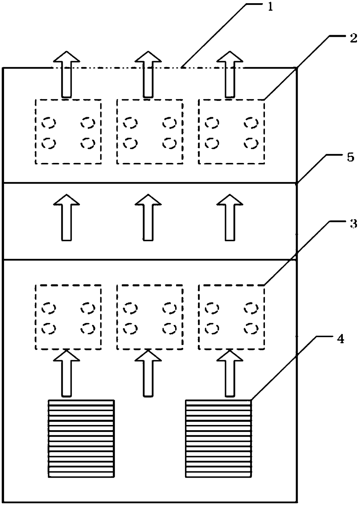
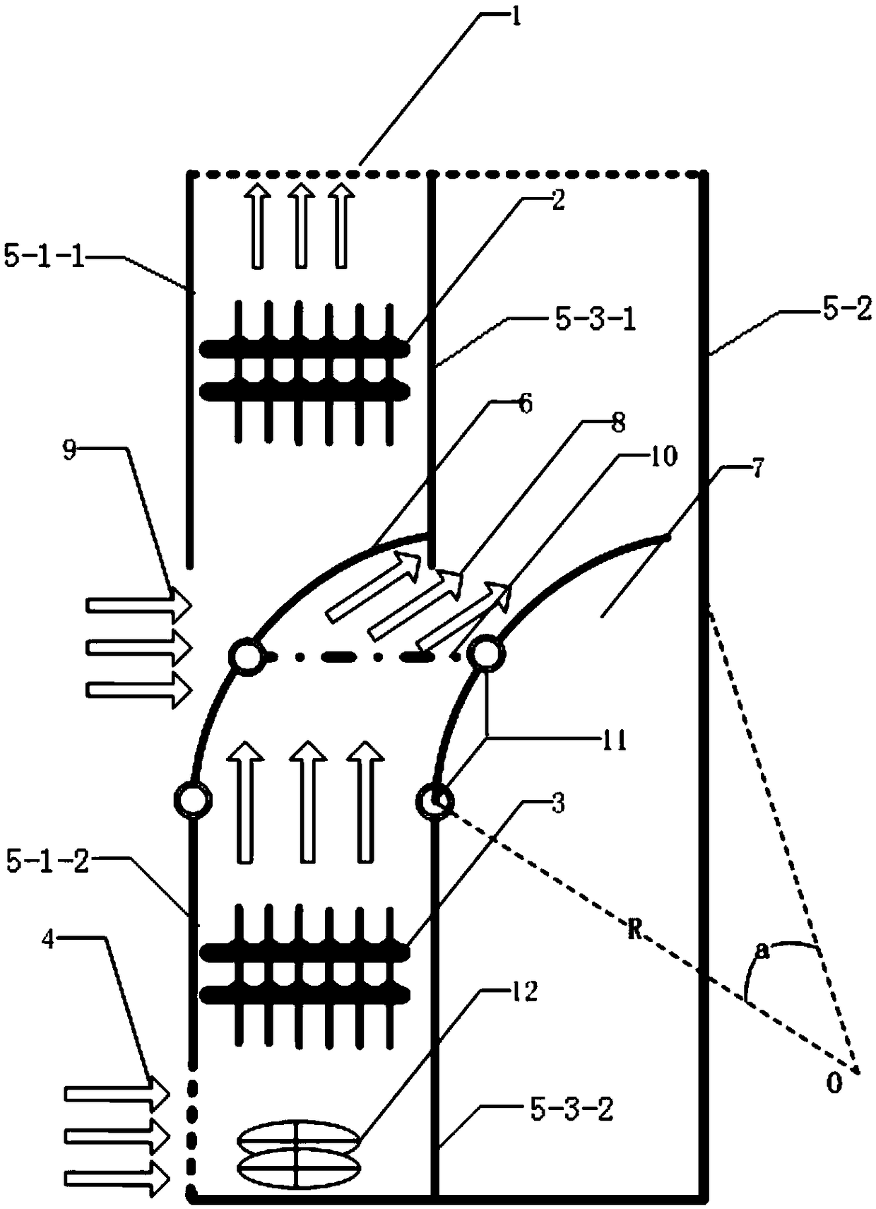
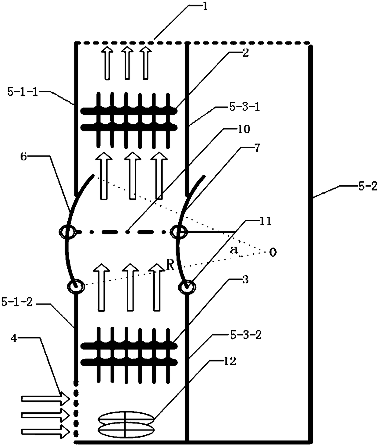
[0019] see figure 1 , a self-cooling heat pipe heat dissipation power cabinet air duct automatic switching device of the present invention includes a cabinet body 5, an upper heat pipe radiator 2, a lower heat pipe radiator 3, and a fan 12. The cabinet body 5 comprises a front plate, a back plate 5-2 and an intermediate plate between the front plate and the back plate 5-2; the front plate comprises an upper front plate 5-1-1 and a lower front plate 5-1-2, the lower The top of the front plate 5-1-2 is connected with a front wind deflector 6; the middle plate includes an upper middle plate 5-3-1 and a lower middle plate 5-3-2, and the top of the lower middle plate 5-3-2 is connected with a rear Air deflector 7; front air deflector 6 connects rear a...


PUM


Abstract

The invention discloses a self-hot-and-cold tube heat dissipation power cabinet air duct automatic switching device which comprises a cabinet body, an upper heat tube heat dissipator, a lower heat tube heat dissipator and a fan. The cabinet body comprises a front plate, a rear plate and a middle plate located between the front plate and the rear plate. The front plate comprises an upper front plate and a lower front plate. The top of the lower front plate is connected with a front air deflector. The middle plate comprises an upper middle plate and a lower middle plate. The top of the lower middle plate is connected with a rear air deflector. The front air deflector is connected with the rear air deflector through front and rear air deflector connection rods. The upper heat tube heat dissipator is located in a first area between the upper front plate and the upper middle plate. The lower heat tube heat dissipator is located in a second area between the lower front plate and the lower middle plate. The fan is located below the lower heat tube heat dissipator. According to the invention, the air duct switching method is simple and reliable; the influence of the heating of a lower thyristor component on the temperature rise of an upper thyristor component in a traditional air duct is eliminated; the heat dissipation efficiency of a self-hot-and-cold tube heat dissipation power cabinet is improved; and the output current is improved.

Description

technical field [0001] The invention relates to an automatic air duct switching device of a self-cooling and heat pipe heat dissipation power cabinet, belonging to the technical field of self-cooling and heat pipe heat dissipation power cabinets. Background technique [0002] In the self-cooling and heat pipe cooling power cabinet, six groups of thyristor components of the three-phase full-control rectifier bridge are installed in upper and lower layers. Three groups of upper positive bridge arms are installed in the upper heat pipe radiator air duct, and three lower layer negative bridge arms are installed in the lower layer. Inside the heat pipe radiator air duct. Under normal circumstances, the heat generated by the thyristor is taken away through the heat exchange between the heat pipe, the fins and the air. The front bottom of the cabinet is provided with the air inlet 4 at the bottom of the cabinet, and the top of the cabinet is provided with the air outlet 1 on the t...

Claims


Application Information

Patent Timeline
Patent Type & Authority Patents(China)
IPC IPC(8): H02M7/00H05K7/20
CPCH02M7/003H05K7/20909H05K7/20918H05K7/20936
Inventor 邵宜祥万泉余振施乃川刘丽丽木刚
Owner NARI TECH CO LTD
Why Eureka
Try Eureka