Heat sink arrangement method and heat sink for power device heat sink

A technology for power devices and heat sinks, which is applied in the field of heat sink arrangement methods and heat sinks, can solve problems such as limited heat dissipation capacity, heat sink molding, and difficulty in realizing the process of inserting and inserting teeth, so as to eliminate the influence of temperature rise Effect

Inactive Publication Date: 2017-02-08
湖南智热技术股份有限公司
View PDF7 Cites 0 Cited by
  • Summary
  • Abstract
  • Description
  • Claims
  • Application Information

AI Technical Summary

Problems solved by technology

The existing main method to increase the heat sink area is to use porous heat sinks or corrugated fins to increase the heat dissipation area. However, in addition to the defects of large flow resistance and large temperature difference between the power device heat sinks of the air inlets, there are also the following two defects: : First, as the height of the heat sink increases, the efficiency of the heat sink is low; second, the heat sink cannot be formed with an integral profile, and can only use the technology of inserts or teeth; but if in order to increase the heat dissipation area, the distance between the heat sinks is reduced, Difficulties in realizing the chip and tooth insert process will increase, resulting in unstable quality. Therefore, the minimum spacing between the heat sinks of the existing profiles and (insert) sheet radiators is more than 2.5mm, and the heat dissipation capacity is limited. When the power density is higher, Only radiators that use other methods
[0008] Although the above-mentioned patents all relate to heat sinks and also mention the installation of heat sinks, they do not involve how to improve the arrangement of heat sinks so that when multiple power devices are arranged on the same heat sink at the same time, The heat dissipation effect of each power device is the same to ensure the uniformity of heat dissipation of the power device, so there are still some problems mentioned above, so it is necessary to further improve this

Method used


Image

  • Heat sink arrangement method and heat sink for power device heat sink
  • Heat sink arrangement method and heat sink for power device heat sink
  • Heat sink arrangement method and heat sink for power device heat sink

Examples


Embodiment 1

[0040] An aluminum uniform temperature radiator: the radiator is composed of a base plate, a heat sink and a top plate. Through the combination of aluminum plates of different numbers and thicknesses, different distances between the heat sinks are formed in the direction from the air inlet to the air outlet of the radiator. By adjusting The distance between the heat sinks eliminates the influence of different wind temperatures from the air inlet to the air outlet on the temperature rise of the power devices, and realizes the uniform temperature of the power devices. The scheme of brazing aluminum heat sink is detailed as follows:

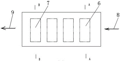
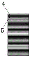
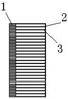
[0041] as attached Figure 1-3 As shown, the entire power device heat sink includes the base plate 1 and the heat sink. The heat sink is formed by a combination of pure aluminum and pure aluminum cladding material plates of different thicknesses, sizes, and shapes. Every two heat sinks, that is, the distance between the first heat sink 2 and the se...


PUM


Abstract

The invention discloses a layout method for radiating fins of a power device radiator and the radiator. According to the method, the radiating fins of the radiator are arrayed according to different thicknesses and different intervals, radiating areas at different positions of a radiator substrate are changed, heat exchange heat resistance of the radiator is reduced and heat performance of the radiator is improved by increasing the area of local radiating fins per unit volume of the radiator, therefore, the total radiating quantities at different positions of the radiator are the same, and the effect of even radiating can be achieved for all power devices. Through the layout method of adjusting the radiating fins and through the combination of aluminum plates in different numbers and different thicknesses, different radiating fin intervals can be formed in the direction from an air inlet to an air outlet of the radiator, the influence of temperature rise on the power devices due to difference of air temperatures in the direction from the air inlet to the air outlet is eliminated through adjusting the intervals of the radiating fins, and temperature uniformity of the power devices can be achieved.

Description

technical field [0001] The invention relates to a design, processing and manufacturing method of a power device heat sink and the heat sink, especially for a heat sink arrangement method and a heat sink for installing multiple power semiconductor devices on a heat sink, which is mainly used for large power devices above 200A. Power thyristors, thyristors and rectifier modules above 25A, and high-power IGBTs above 50A. Background technique [0002] High-power semiconductor devices will generate a lot of heat during operation. In order not to burn out the power device, it is now necessary to use a radiator to help it dissipate heat; among them, the heat sink is a commonly used radiator. The heat sink mainly carries the heat transfer and heat dissipation functions of the power device. [0003] The current heat sink type radiator is basically combined by two units, the heat sink and the base plate, the heat sink mainly plays the role of heat dissipation, and the base plate play...

Claims


Application Information

Patent Timeline
Patent Type & Authority Patents(China)
IPC IPC(8): H05K7/20
Inventor 李纯廖向前封红燕万汝斌
Owner 湖南智热技术股份有限公司
Why Eureka
Try Eureka