Assembly mechanism for easy cylinder mounting parts
A technology for installing components and assembly mechanisms, applied in the direction of transportation and packaging, load hanging components, etc., can solve the problems of casualties and property losses, affect the service life of the suspension rope, and the weight of the rotor, etc., to protect the safety of workers and property The effect of safety, improving service life, reducing friction frequency and friction force
- Summary
- Abstract
- Description
- Claims
- Application Information
AI Technical Summary
Problems solved by technology
Method used
Image

Examples
Embodiment 1
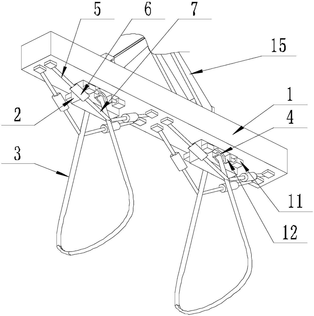
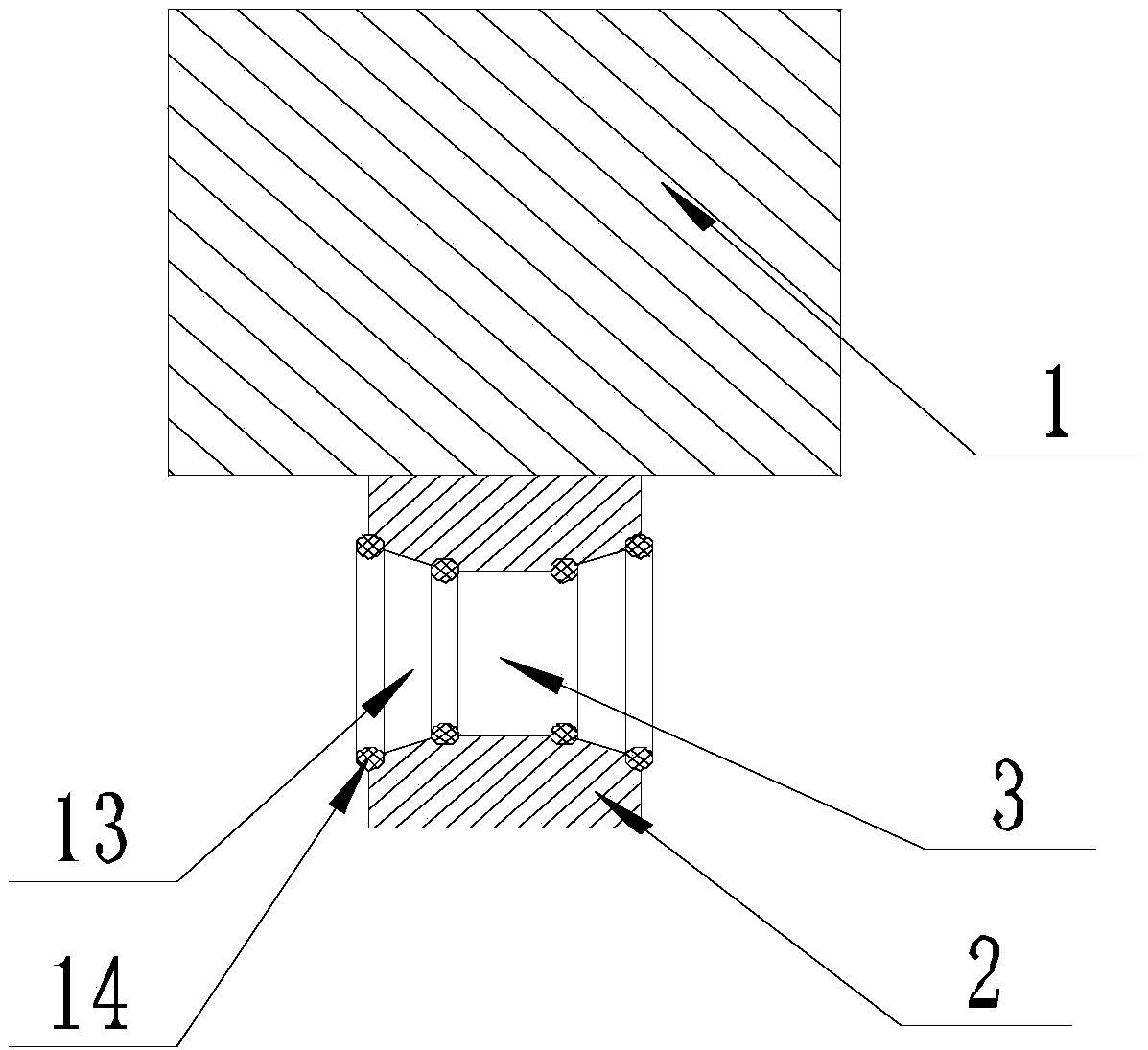
[0044] Such as Figure 1-Figure 6As shown, the present invention facilitates the assembly mechanism of the cylinder mounting parts, including a pair of suspension ropes 3 and a suspension plate 1 that is symmetrically provided with a pair of connection blocks 2 on the lower surface, the suspension ropes 3 are respectively connected with a connection block 2, and the suspension ropes One end of 3 passes through the through hole 4 of connecting block 2 and is connected with the other end, and the upper surface of hanging plate 1 is connected with driving through connecting rope 15 . Both ends of the through hole 4 are provided with several pairs of limiting devices, and each pair of limiting devices is symmetrical along the axis passing through the through hole 4 and perpendicular to the plane of the ground;
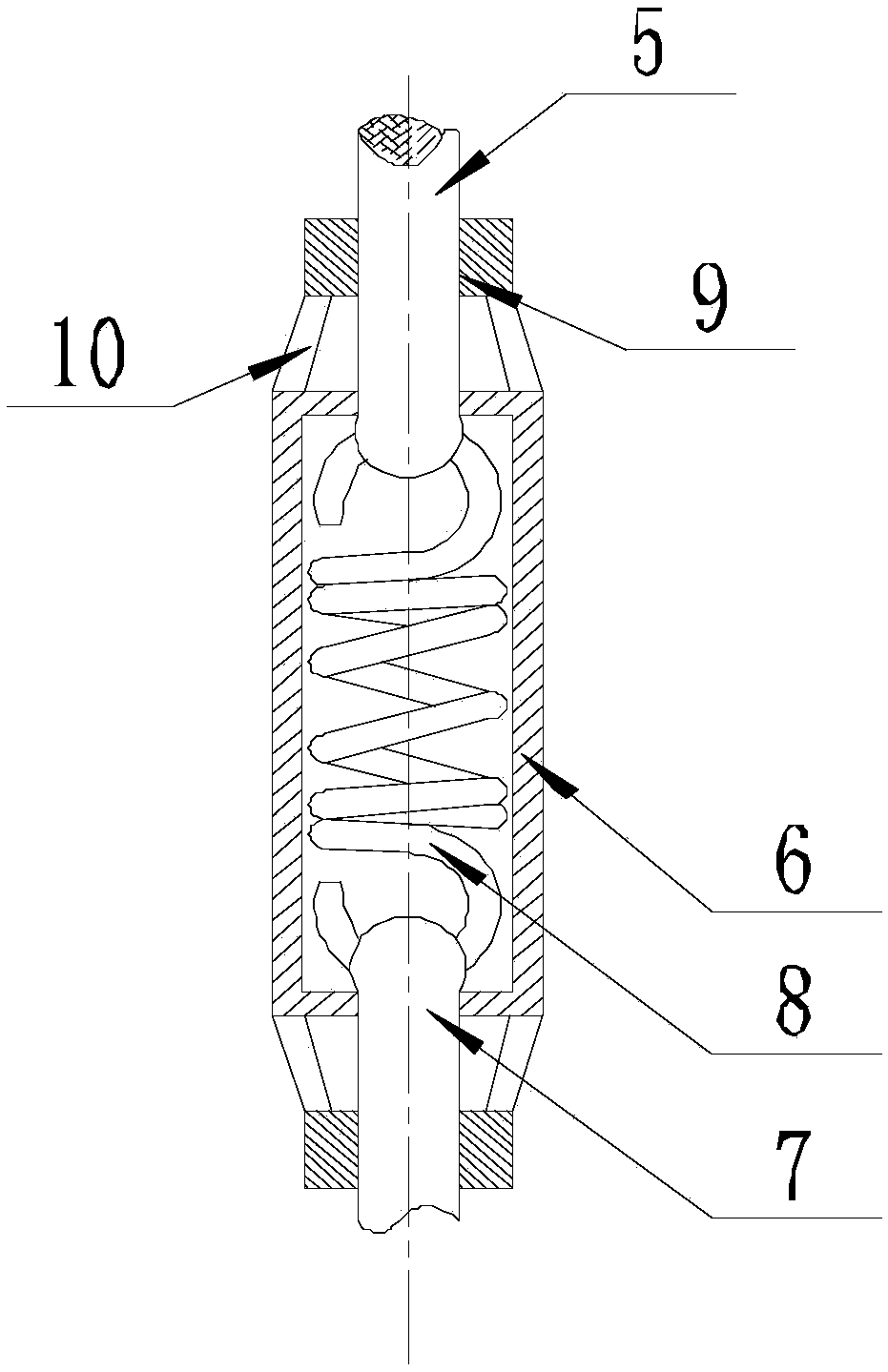
[0045] The limiting device includes a fixed rope 5, a connecting cylinder 6 and a limiting rope 7 connected in sequence, one end of the fixed rope 5 is connected to the ha...
Embodiment 2
[0050] The present invention is based on embodiment 1, and the present invention is further described.
[0051] Such as Figure 1-Figure 6 As shown, the present invention is convenient for the assembly mechanism of the cylinder installation parts, and the end of the fixed rope 5 close to the connecting cylinder 6 and the end of the limiting rope 7 close to the connecting cylinder 6 are all sleeved with a limit ring 9, and the limit rings 9 are all sleeved. It is connected with the connecting cylinder 6 through several connecting arms 10 with the axis of the connecting cylinder 6 as the central symmetry line.
[0052] An elastic rubber layer is provided on the inner wall of the limiting ring 9 .
[0053] Since one end of the fixed rope 5 and the limit rope 7 is located in the connecting cylinder 6, when the suspension rope 9 is used or moved, the parts where the fixed rope 5 and the limiting rope 7 are in contact with the port of the connecting cylinder 6 will be subject to fr...
Embodiment 3
[0055] The present invention is based on embodiment 1, and the present invention is further described.
[0056] Such as Figure 1-Figure 6 As shown, the present invention facilitates the assembly mechanism of the cylinder mounting parts. A pair of pneumatic cylinders 11 are arranged at both ends of the through hole 4, and each pair of pneumatic cylinders 11 is symmetrical along the axis passing through the through hole 4 and perpendicular to the plane of the ground, and The axis of the pneumatic cylinder 11 is parallel to the horizontal plane, and the end of the piston rod of the pneumatic cylinder 11 faces the axis of the through hole 4 .
[0057] At the end of the piston rod of the pneumatic cylinder 11, a limiting plate 12 is arranged, and the piston rod is stretched out, so that the limiting plate 12 can be contacted with the suspension rope 3 .
[0058] The setting of the pneumatic cylinder 11 further limits the shaking of the suspension rope 3 and prevents the suspensio...
PUM
 Abstract
Description
Claims
Application Information
 - R&D
- Intellectual Property
- Life Sciences
- Materials
- Tech Scout
- Unparalleled Data Quality
- Higher Quality Content
- 60% Fewer Hallucinations
Browse by: Latest US Patents, China's latest patents, Technical Efficacy Thesaurus, Application Domain, Technology Topic, Popular Technical Reports.
© 2025 PatSnap. All rights reserved.Legal|Privacy policy|Modern Slavery Act Transparency Statement|Sitemap|About US| Contact US: help@patsnap.com