Optical fiber adapter

A fiber optic adapter and fiber optic connector technology, applied in light guides, optics, instruments, etc., can solve problems such as high manufacturing costs and complex structures

Active Publication Date: 2017-09-26
PROTAI PHOTONIC
View PDF6 Cites 4 Cited by
  • Summary
  • Abstract
  • Description
  • Claims
  • Application Information

AI Technical Summary

Problems solved by technology

However, if only light-shielding and dust-proof functions are required, the above-mentioned protect

Method used


Image

  • Optical fiber adapter
  • Optical fiber adapter
  • Optical fiber adapter

Examples


Embodiment Construction

[0105] refer to Figure 4a and 4b , which respectively show a well-known male MPO fiber optic connector 400a and a female MPO fiber optic connector 400b. An elongated protrusion 412 is formed on the upper surface 410 of the front section of the fiber optic connectors 400 a and 400 b , and recesses 414 are formed on both sides of the front section. A plurality of optical fibers 430 are exposed on the end faces 420 of the front ends of the optical fiber connectors 400a and 400b, wherein the end faces of the optical fibers 430 are flush with the end faces 420 of the optical fiber connectors 400a and 400b. In addition, two guiding holes 450 are formed on the end surface 420 of the optical fiber connector 400b, and a pair of guiding pins 440 protrude from the end surface 420 of the optical fiber connector 400a, which can be inserted into the guiding holes 450 respectively.

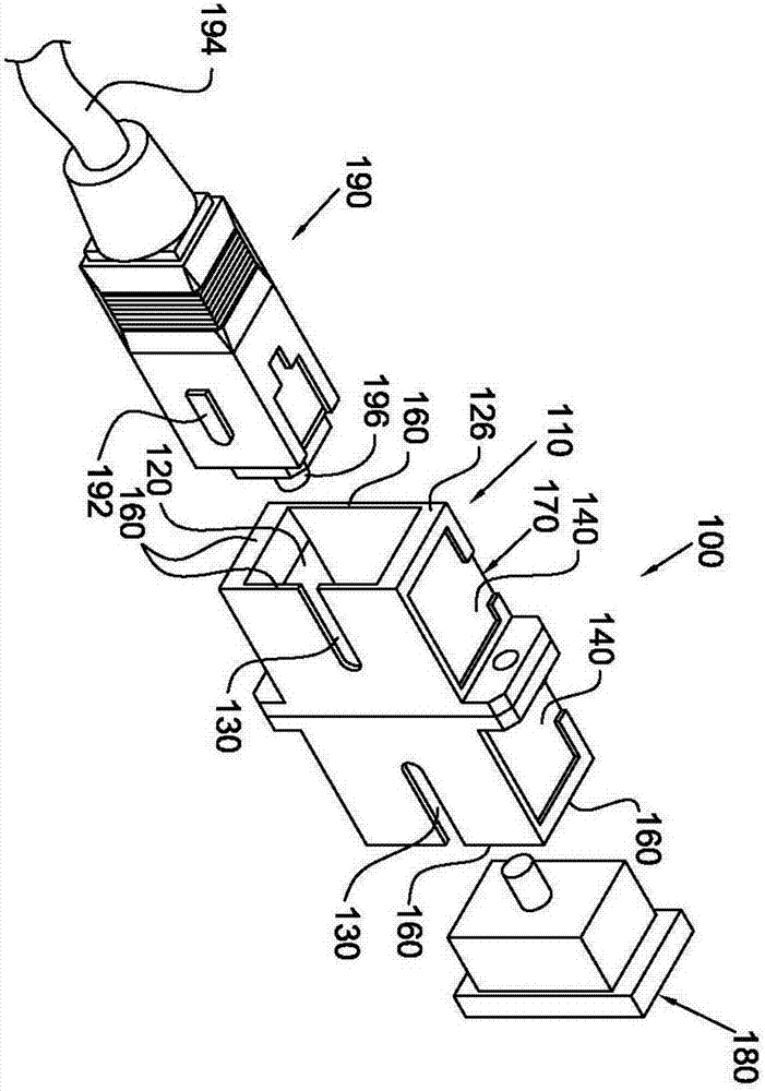
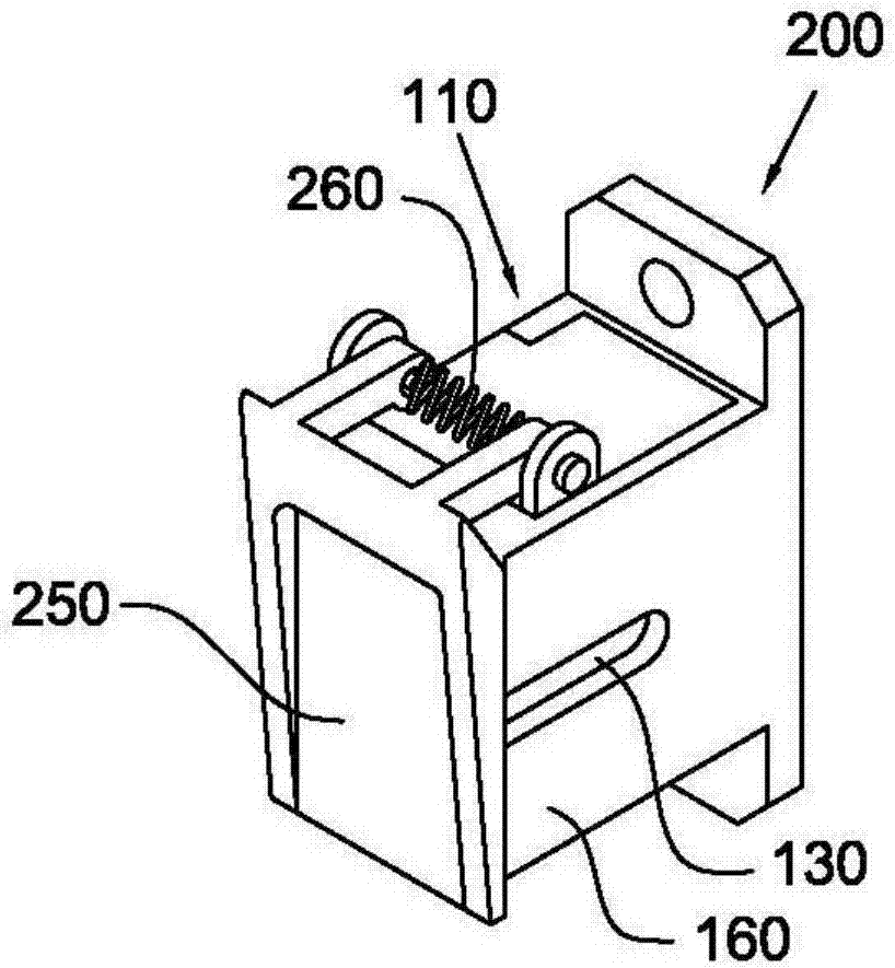
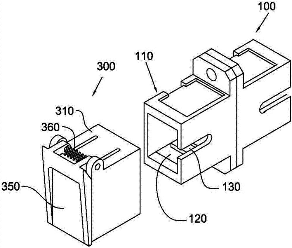
[0106] Please refer to Figures 5a to 8d , the optical fiber adapter with shading element of the present ...


PUM


Abstract

An optical fiber adapter of the present invention comprises a main body, two first hooks, a first light blocking member, a second light shielding member and an inner case. The first hooks are respectively extended by the second and fourth walls of the body. The first light blocking member is disposed in the body from the first opening of the body, and the first light shielding member includes a first base portion, a first light shielding portion, and a first connection portion. The first base portion is provided on the first wall of the body, and the first connection portion is connected to the first light shielding portion and the first base portion. The second light-blocking member is disposed in the body from the first opening of the body, and the second light-blocking member includes a second base portion, a second light-shielding portion, and a second connection portion. The second base portion is provided on the third wall of the body, and the second connection portion is connected to the second light shielding portion and the second base portion. The inner housing is placed in the body from the first opening of the body.

Description

technical field [0001] The present invention relates to an optical fiber adapter, more particularly to an optical fiber adapter with a light-shielding member. Background technique [0002] Due to the advantages of high bandwidth and low loss, optical fiber has been widely used as a signal transmission medium in recent years. In order to enable the signal to be transmitted to a longer distance, high-power laser diodes are born, thus greatly increasing the energy coupled to the optical fiber. However, when the above-mentioned high-intensity infrared beam is emitted from one end of the optical fiber, the human eye cannot judge the existence of the beam. If the operator's eyes are accidentally exposed to the beam, it will often cause permanent damage to vision. [0003] Please refer to figure 1 , the well-known optical fiber adapter (optical fiber adapter) 100 has a main body 110, and the main body 110 is provided with a chamber 120 surrounded by a plurality of side walls 160,...

Claims


Application Information

Patent Timeline
IPC IPC(8): G02B6/38
CPCG02B6/3825G02B6/3849
Inventor 杨至诚陈裕楷
Owner PROTAI PHOTONIC
Why Eureka
Try Eureka