Unlock instant, AI-driven research and patent intelligence for your innovation.
Image defogging method based on concentration feature of fog
What is Al technical title?
Al technical title is built by PatSnap Al team. It summarizes the technical point description of the patent document.
A fog and concentration technology, applied in image enhancement, image analysis, image data processing, etc., can solve problems such as poor robustness, inapplicability to foggy images, and low positioning accuracy in atmospheric light areas
Active Publication Date: 2017-09-26
南京云开数据科技有限公司
View PDF6 Cites 19 Cited by
Summary
Abstract
Description
Claims
Application Information
AI Technical Summary
This helps you quickly interpret patents by identifying the three key elements:
Problems solved by technology
Method used
Benefits of technology
Problems solved by technology
[0007] The technical problem solved by the present invention is: the existing image defogging method has low positioning accuracy for the atmospheric light area in the foggy image, cannot be applied to various foggy images, and has poor robustness
Method used
Image
Click on the blue label to locate the original text in one second.
Reading with bidirectional positioning of images and text.
Examples
Embodiment 1
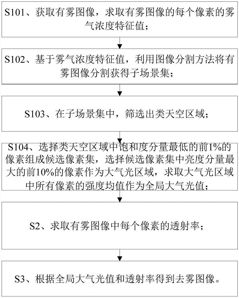
[0055] Embodiment 1 of the present invention proposes an image defogging method based on fog density features, such as figure 1 shown, including the following steps:
[0056] S1, locate the atmospheric light area in the foggy image, and calculate the global atmospheric light value, including:
[0057] S101. Obtain a foggy image, and calculate the fog concentration feature value of each pixel of the foggy image according to the following formula:
[0058]
[0059] Among them, S(x, y) represents the fog concentration feature value of the pixel (x, y) in the foggy image, I'(x, y) represents the brightness component of the pixel (x, y), Represents the gradient component of the pixel (x, y), I°(x, y) represents the saturation component of the pixel (x, y), γ 1 Indicates the brightness weight, γ 2 Indicates the gradient weight, γ 3 Indicates the saturation weight, γ 4 Indicates the quantization error compensation value.
[0060] During specific processing, set γ 1 = 0.931...
Embodiment 2
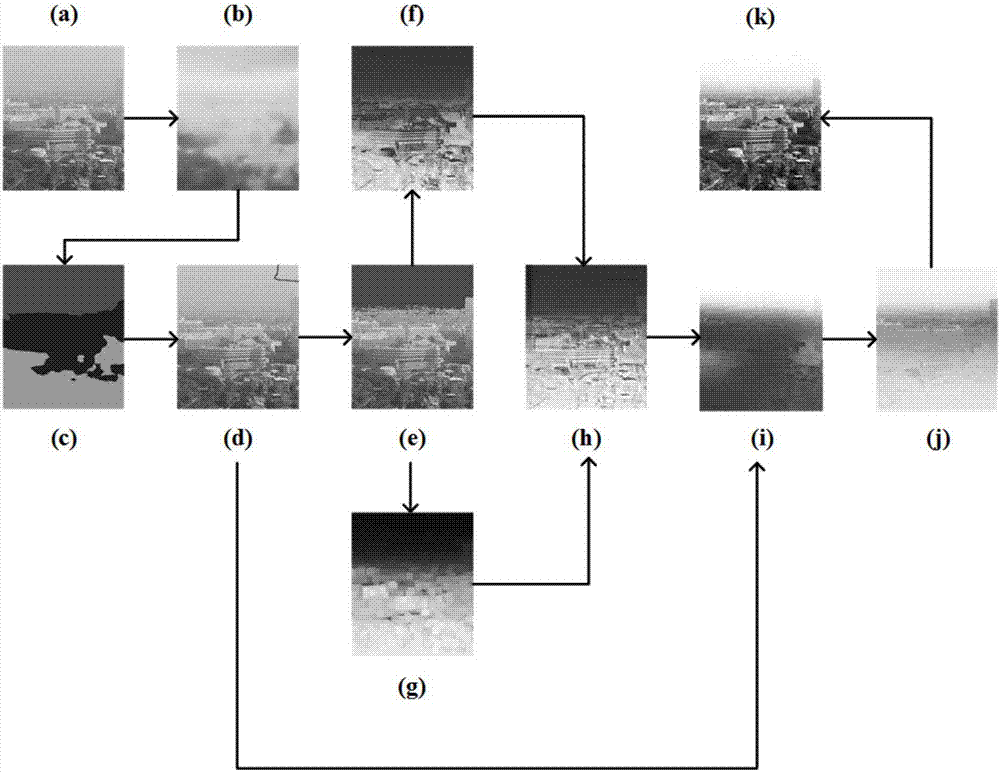
[0079] figure 2 It is a flow chart of Embodiment 2 of the present invention specifically applied in the defogging process of a foggy image. There are effect diagrams of each step in the figure, combined with figure 2 Embodiment 2 of the present invention will be described in detail.
[0080] Embodiment 2 of the present invention proposes an image defogging method based on fog concentration features, including the following steps:
[0081] S1, locate the atmospheric light area in the foggy image, and calculate the global atmospheric light value, including:
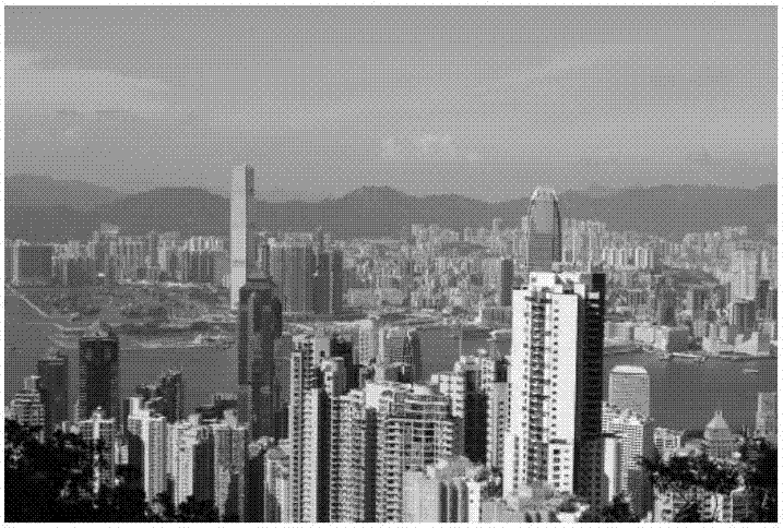
[0082] S101. Obtain a foggy image, such as figure 2 (a), calculate the fog concentration feature value of each pixel of the foggy image according to the following formula:
[0083]
[0084] Among them, S(x, y) represents the fog concentration feature value of the pixel (x, y) in the foggy image, I'(x, y) represents the brightness component of the pixel (x, y), Represents the gradient component of the intensity of...
PUM
Abstract
The invention provides an image defogging method based on the concentration feature of fog, comprising the following steps: calculating the fog concentration feature value of each pixel in a foggy image; segmenting the foggy image to get a sub scene set through an image segmentation method based on the fog concentration feature values; screening out a sky-like area from the sub scene set; selecting the first 1% pixels with lowest saturation component in the sky-like area to form a candidate pixel set, selecting the first 10% pixels with highest saturation component in the candidate pixel set to form an atmospheric light area, and calculating the average intensity value of all the pixels in the atmospheric light area as a global atmospheric light value; calculating the transmittance of each pixel in the foggy image; and getting a defogged image according to the global atmospheric light value and the transmittance. The atmospheric light area can be located accurately in the defogging process. The method is less susceptible to highlighted noise points or interference in the foggy image. Therefore, an accurate global atmospheric light value is obtained, and a better defogging effect is achieved. The image defogging method is used to defog a variety of foggy images, and is of high robustness.
Description
technical field [0001] The invention specifically relates to an image defogging method based on fog concentration characteristics, and belongs to the technical field of image defogging processing. Background technique [0002] In the foggy environment, due to the influence of suspended particles in the atmosphere, the images collected by imaging equipment have poor visibility, low saturation, and serious lack of clarity. Therefore, it is of great practical significance to sharpen the degraded image in foggy weather. [0003] Among the image defogging methods, the image defogging method based on the atmospheric scattering model is the most effective and the most common. This type of method uses the atmospheric scattering model to describe the imaging process under haze weather conditions. The atmospheric scattering model based on it is as follows: [0004] I(x,y)=L ∞ ·J(x,y)+L ∞ ·(1-t(x,y)) [0005] Among them, I(x,y) represents the intensity value of pixel (x,y) in the f...
Claims
Application Information
Patent Timeline
Application Date:The date an application was filed.
Publication Date:The date a patent or application was officially published.
First Publication Date:The earliest publication date of a patent with the same application number.
Issue Date:Publication date of the patent grant document.
PCT Entry Date:The Entry date of PCT National Phase.
Estimated Expiry Date:The statutory expiry date of a patent right according to the Patent Law, and it is the longest term of protection that the patent right can achieve without the termination of the patent right due to other reasons(Term extension factor has been taken into account ).
Invalid Date:Actual expiry date is based on effective date or publication date of legal transaction data of invalid patent.

