
Flashlight component and terminal equipment

A terminal equipment and flash technology, applied in branch equipment, equipment with functional cameras, optics, etc., can solve problems such as difficulty in precise control, influence of distance assembly accuracy, poor lighting effect of flash, etc., to ensure air gap and optimize illumination. effect, the effect of a good optical effect

Inactive Publication Date: 2017-09-26
MEIZU TECH CO LTD
View PDF5 Cites 5 Cited by
  • Summary
  • Abstract
  • Description
  • Claims
  • Application Information

AI Technical Summary

Problems solved by technology

[0002] In the mobile phones currently on the market, the flash light is fixedly arranged on the main board, and the flash cover is often embedded in the bottom cover, and the bottom cover is covered on the main board. The relative position of the flash cover in the bottom cover indirectly limits the distance between the flash cover and the main board. The distance between the flash cover and the flash is affected by the assembly accuracy of the main board and the bottom cover, which is difficult to control accurately, resulting in poor lighting effect of the flash

Method used


Image

  • Flashlight component and terminal equipment
  • Flashlight component and terminal equipment

Examples


Embodiment Construction

[0035] In order to understand the above-mentioned purpose, features and advantages of the present invention more clearly, the present invention will be further described in detail below in conjunction with the accompanying drawings and specific embodiments. It should be noted that, in the case of no conflict, the embodiments of the present application and the features in the embodiments can be combined with each other.

[0036] In the following description, many specific details are set forth in order to fully understand the present invention. However, the present invention can also be implemented in other ways different from those described here. Therefore, the protection scope of the present invention is not limited by the specific details disclosed below. EXAMPLE LIMITATIONS.

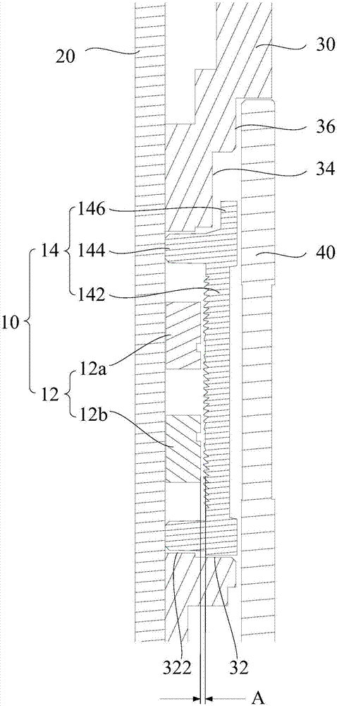
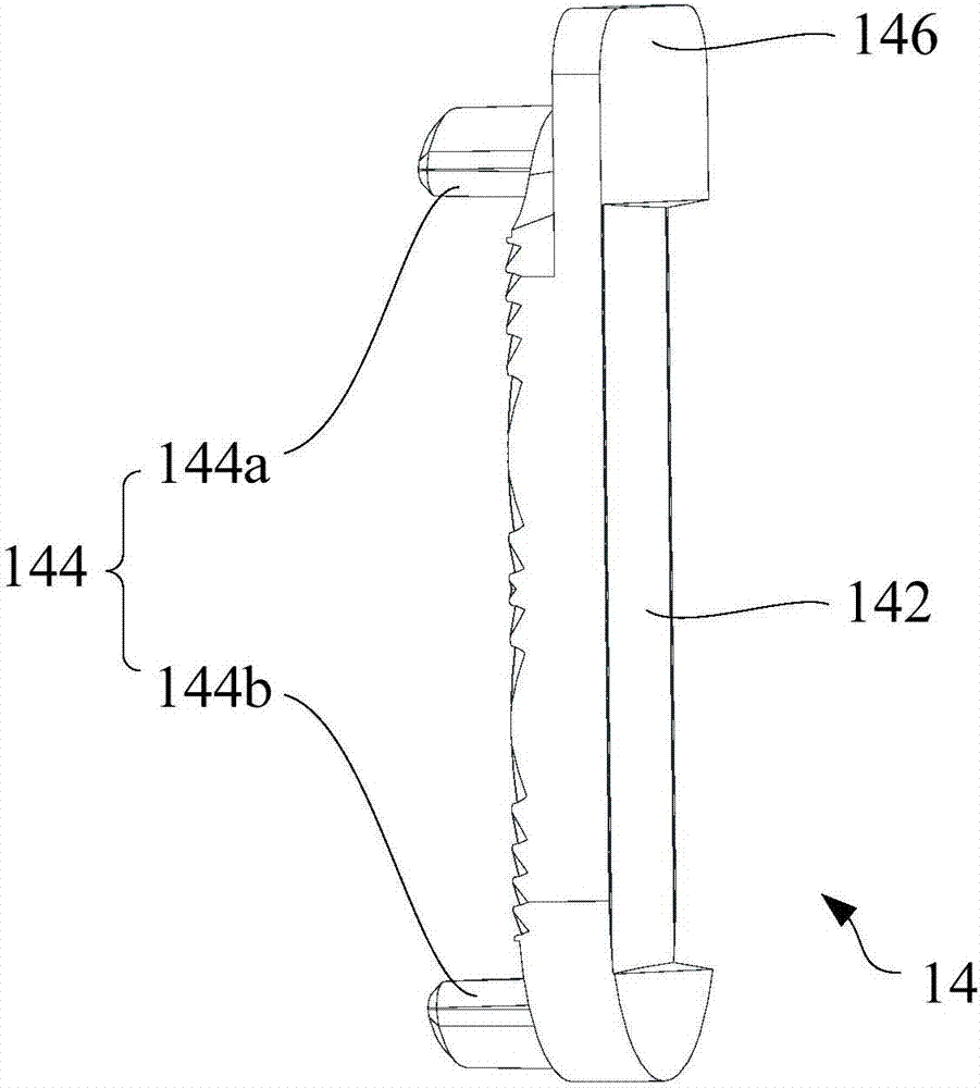
[0037] Refer below figure 1 and figure 2 The flash unit 10 and the terminal device according to some embodiments of the present invention are described.

[0038] Such as figure 1 and figure 2A...


PUM


Abstract

The invention provides a flashlight component and terminal equipment applying the same. The terminal equipment comprises a main plate and a cover body; the cover body covers the main plate and is provided with a mounting hole; the flashlight component comprises at least one flashlight and a flashlight shade, wherein the flashlight is arranged on one side, facing to the cover plate, of the main plate and is positioned in the mounting hole; the flashlight shade is positioned in the mounting hole, the flashlight is positioned between the main plate and the flashlight shade, the flashlight shade comprises a shade body arranged with the main plate in parallel and at least one positioning column, the cover shade is matched with the mounting hole, and the positioning column extends from the shade body to the main plate and is propped against the main plate. The flashlight component provided by the invention has the benefits that in a mounting state, the shade body is arranged on the flashlight in a covering manner; the positioning column is propped against the main plate, so that the shade body and the main plate can be directly propped against the positioning column to limit a space, further a space between the shade body and the flashlight is accurately controlled, and the radiation effect of the flashlight is optimized.

Description

technical field [0001] The present invention relates to the technical field of electronic equipment, in particular, to a flash light assembly and a terminal equipment. Background technique [0002] In the mobile phones currently on the market, the flash light is fixedly arranged on the main board, and the flash cover is often embedded in the bottom cover, and the bottom cover is covered on the main board. The relative position of the flash cover in the bottom cover indirectly limits the distance between the flash cover and the main board. The distance between the flash lamp cover and the flash lamp is affected by the assembly accuracy of the main board and the bottom cover, and it is difficult to accurately control, resulting in poor lighting effect of the flash lamp. Contents of the invention [0003] The present invention aims to solve at least one of the technical problems existing in the prior art or related art. [0004] To this end, a first aspect of the present inv...

Claims


Application Information

Patent Timeline
Patent Type & Authority Applications(China)
IPC IPC(8): H04M1/02G03B15/05
CPCH04M1/0264G03B15/05H04M2250/52
Inventor 梁师旭甘志高
Owner MEIZU TECH CO LTD
Learn More