Touch pad antenna device and electronic apparatus

A technology for antenna devices and electronic equipment, applied to antennas, antenna couplings, antenna parts, etc., can solve problems such as difficulty in ensuring antenna communication performance and shielding of radio waves, and achieve operational performance, maintain operational performance, and ensure communication performance. Effect

Active Publication Date: 2017-09-26
DEXERIALS CORP
View PDF8 Cites 2 Cited by
  • Summary
  • Abstract
  • Description
  • Claims
  • Application Information

AI Technical Summary

Problems solved by technology

However, in notebook computers that are becoming smaller and thinner, the casing is often made of metal, which shields radio waves, making it difficult to ensure the communication performance of the antenna

Method used


Image

  • Touch pad antenna device and electronic apparatus
  • Touch pad antenna device and electronic apparatus
  • Touch pad antenna device and electronic apparatus

Examples


no. 1 approach

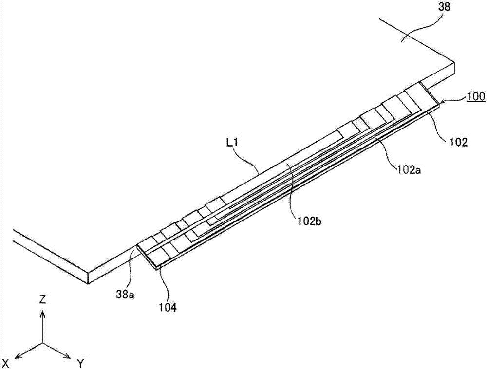
[0063] Next, the configuration of the antenna device for a touch panel according to the first embodiment of the present invention will be described with reference to the drawings. Figure 3A is a perspective view showing a schematic configuration of the antenna device for a touch panel according to the first embodiment of the present invention, Figure 3B It is a side view showing a schematic configuration of the antenna device according to the first embodiment of the present invention.

[0064] Such as Figure 3A As shown, the antenna device 100 for a touch panel includes: conductive wires 102a facing each other in the width direction across an opening 102b are wound and arranged so as to be close to each other, and are connected to an external device 50 (refer to Figure 3B ) inductively coupled antenna coil 102 . The antenna coil 102 is formed by patterning a flexible conductive wire 102 a on one side of an antenna substrate 101 composed of a flexible flexible substrate o...

no. 2 approach

[0074] Next, the configuration of the antenna device for a touch panel according to the second embodiment of the present invention will be described with reference to the drawings. Figure 5A is a perspective view showing a schematic configuration of an antenna device for a touch panel according to a second embodiment of the present invention, Figure 5B It is a side view showing a schematic configuration of the antenna device according to the second embodiment of the present invention.

[0075] Such as Figure 5A As shown, the antenna device 200 for a touch panel includes: conducting wires 202a facing each other in the width direction across an opening 202b are wound and arranged so as to be close to each other, and are connected to an external device 50 (refer to Figure 5B ) inductively coupled antenna coil 202 . The antenna coil 202 is formed by patterning a flexible conductive wire 202 a on one side of an antenna substrate 201 composed of a flexible flexible substrate o...

no. 3 approach

[0084] Next, the structure of the antenna device for touch panels which concerns on 3rd Embodiment of this invention is demonstrated using drawing. Figure 7A is a perspective view showing a schematic configuration of an antenna device for a touch panel according to a third embodiment of the present invention, Figure 7B It is a side view showing a schematic configuration of an antenna device according to a third embodiment of the present invention.

[0085] Such as Figure 7A As shown, the antenna device 300 for a touch panel includes: conducting wires 302a facing each other in the width direction across an opening 302b are wound and arranged so as to be close to each other, and are connected to an external device 50 (refer to Figure 7B ) inductively coupled antenna coil 302 . The antenna coil 302 is formed by patterning a flexible conductive wire 302 a on one side of an antenna substrate 301 made of a flexible flexible substrate or the like.

[0086] In this embodiment, ...


PUM


Abstract

To ensure communication performance of an antenna with a reduced antenna size, while maintaining operation performance of a touch pad. Disclosed is a touch pad antenna device (100), which is provided along with a capacitance type touch pad (10) mounted in an electronic apparatus (1), and which communicates with an external apparatus by means of electromagnetic field signals. The touch pad antenna device is provided with an antenna coil (102) wherein conducting wires (102a) facing each other in the width direction with an opening (103) therebetween are provided by being wound such that the conducting wires are close to each other, said antenna coil being inductively coupled to the external apparatus, and the antenna coil is provided along an outer end (38a) of a sheet-like electrode section (38) that constitutes the touch pad.

Description

technical field [0001] The present invention relates to an antenna device for a touch panel in which a capacitive touch panel mounted on electronic equipment such as a notebook computer and an RFID antenna are integrated, and electronic equipment incorporating the antenna device for a touch panel. This application claims priority based on Japanese Patent Application No. Japanese Patent Application No. 2015-024201 for which it applied in Japan on February 10, 2015, and takes in this application by referring to this application. Background technique [0002] In recent years, technology has been developed to equip electronic devices such as notebook computers with antenna functions such as RFID (radiofrequency identification) to enable communication with external devices such as smartphones. However, in notebook computers that are being reduced in size and thickness, the casings are often made of metal, which shields radio waves, making it difficult to ensure the communication ...

Claims


Application Information

Patent Timeline
Patent Type & Authority Applications(China)
IPC IPC(8): H01Q7/06G06F3/0354G06F3/041G06F3/044H01Q1/52
CPCG06F1/169G06F3/03547H01Q1/2266H01Q7/04H01Q7/06G06F3/0354G06F3/041H01Q1/243H01Q1/52H01Q1/526
Inventor 折原胜久
Owner DEXERIALS CORP
Why Eureka
Try Eureka