Dual mass flywheel

A dual-mass flywheel and flywheel technology, applied in the direction of flywheel, rotation vibration suppression, spring/shock absorber, etc., can solve the problems that the spring cannot be stably and firmly held, and it is impossible to absorb various noises and vibrations, etc., to improve Performance and durability, ensuring competitive results

Inactive Publication Date: 2014-07-02
PHC CO LTD
View PDF5 Cites 11 Cited by
  • Summary
  • Abstract
  • Description
  • Claims
  • Application Information

AI Technical Summary

Problems solved by technology

[0014] In addition, since the spring held by the spring guide uses only a linear coil spring, it is impossible to absorb various noises and vibrations, and the spring guide surrounds the outside of the spring, so the spring cannot be held stably and securely

Method used


Image

  • Dual mass flywheel
  • Dual mass flywheel
  • Dual mass flywheel

Examples


Embodiment Construction

[0026] Hereinafter, exemplary embodiments of the present invention for achieving the above objects will be described with reference to the accompanying drawings.

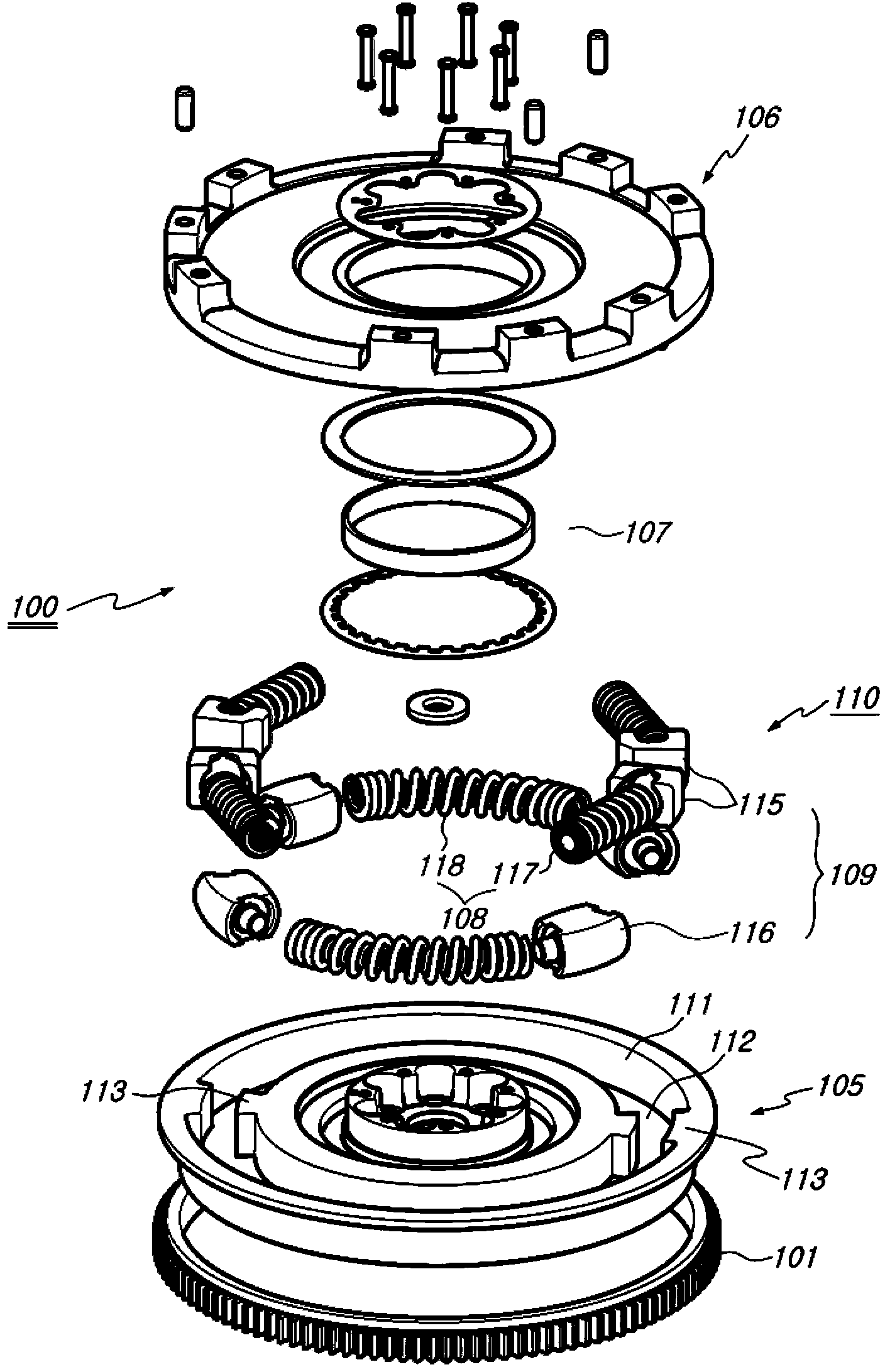
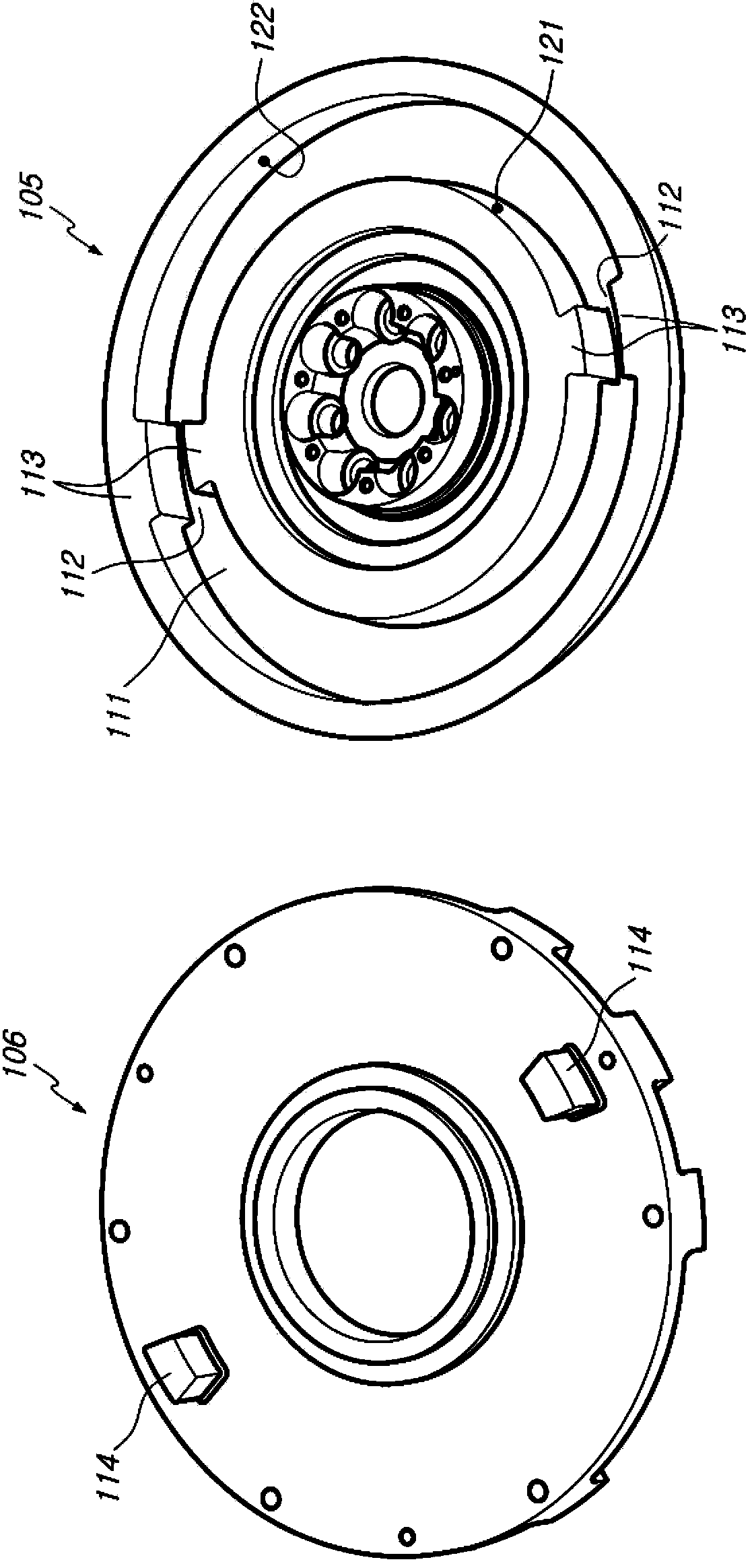
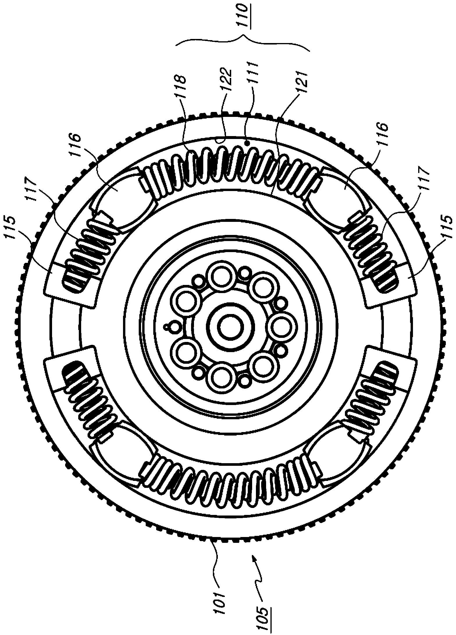
[0027] figure 1 is an exploded perspective view showing a dual mass flywheel according to the present invention. figure 2 is a perspective view showing the top of the dual mass primary flywheel and the bottom of the secondary flywheel according to the present invention. image 3 is a plan view showing a state in which a spring and a spring guide are mounted to the dual mass flywheel according to the present invention. Figure 4 is a perspective view showing a spring guide applied to a dual mass flywheel according to the invention. Figure 5 is a schematic view showing the installation state of the spring guide applied to the dual mass flywheel according to the present invention. Figure 6 is a plan view showing the operating state of the dual mass flywheel according to the present invention.

[0028] Such as ...


PUM


Abstract

A dual mass flywheel includes: a primary flywheel having a ring gear and connected to an output shaft of an engine; a secondary flywheel connected to an input shaft of a transmission; a coupling unit for coupling the primary flywheel and the secondary flywheel; a plurality of drive units coupled to the primary flywheel and the secondary flywheel and in which spring guides are coupled to opposite sides of a torsion spring to dampen noise and vibrations while a torque of the primary flywheel is transferred to the secondary flywheel, a unit groove formed in the primary flywheel to accommodate the drive units; separation prevention bosses formed above and below a center line of the unit groove and having an operation slot therebetween to prevent deviation of the drive units; and driving pins protruding from a bottom surface of the secondary flywheel to compress and damp the drive units, wherein a linear spring and a curved spring of a torsion spring are combined between an end guide and a middle guide or between the middle guides to prevent a contacting point thereof from being pushed to the outside by a centrifugal force when the drive unit is operated.

Description

technical field [0001] The present invention relates to dual mass flywheels, and more particularly to an improved dual mass flywheel which effectively attenuates the shock and noise generated in the process of transmitting the power of the engine to the transmission and at the same time does not results in a loss of torque and has a simpler construction due to the reduced number of parts. Background technique [0002] Dual-mass flywheels (DMF) for vehicles are adapted to dampen the motion caused by the damped operation of the arc springs when the drive plate connecting the primary and secondary flywheels moves in combination with the arc springs mounted to the main mass Shock between the engine and transmission, thereby reducing vibration and noise caused by sudden acceleration of the vehicle, such as gear noise and body roar. [0003] If the driving force of the engine is transmitted to the main mass due to the above-mentioned technical configuration, the driving plate als...

Claims


Application Information

Patent Timeline
Patent Type & Authority Applications(China)
IPC IPC(8): F16F15/30
CPCF16F15/31F16F15/13453Y10T74/2132F16F15/30F16F15/12F16F15/134
Inventor 李春坤金忠钟
Owner PHC CO LTD
Why Eureka
Try Eureka