Novel kitchen storage rack

A technology for placing racks and kitchen utensils, applied in kitchen utensils, home utensils, applications, etc., can solve the problems of being too simple, and the water in the kitchen utensils cannot be well discharged, and achieve the effect of ensuring the service life

Inactive Publication Date: 2017-09-29
过蕊
5 Cites 5 Cited by

AI-Extracted Technical Summary

Problems solved by technology

[0003] The purpose of the present invention is to solve the problem that the structure of the shelf in the prior art is too simple, and lacks the function of freely adjusting the space according to the size of...

Abstract

The invention discloses a novel kitchen storage rack. The novel kitchen storage rack comprises a water storage tank and a storage box, wherein the inner bottom of the storage box is communicated with the inner top of the water storage tank by virtue of a guide pipe, two limiting plates are symmetrically arranged on the inner wall of the guide pipe, the limiting plate is connected with the inner wall of the guide pipe in a rotating manner by virtue of a first rotating shaft, the first rotating shaft is sleeved with a first torsion spring, two ends of the first torsion spring are respectively fixedly connected with the limiting plate and the inner wall of the guide pipe, two ends of the top of the water storage tank and the storage box are fixedly connected by virtue of a plurality of supporting rods, a water outlet is formed in the bottom of one side inner wall of the water storage tank, and the water outlet is internally connected with a water outlet valve in a threading manner. By arranging a separation plate and the water storage tank, when the apparatus is used for storing tableware, the space can be freely adjusted according to the size of the tableware, and water remaining on the tableware can also be well discharged, so that the service life of the apparatus can be ensured.

Application Domain

Technology Topic

Image

  • Novel kitchen storage rack
  • Novel kitchen storage rack
  • Novel kitchen storage rack

Examples

  • Experimental program(1)

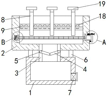
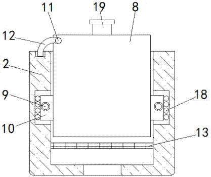
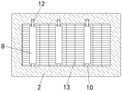
Example Embodiment

[0018] The technical solutions in the embodiments of the present invention will be clearly and completely described below in conjunction with the accompanying drawings in the embodiments of the present invention. Obviously, the described embodiments are only a part of the embodiments of the present invention, rather than all the embodiments.
[0019] In the description of the present invention, it should be understood that the terms "upper", "lower", "front", "rear", "left", "right", "top", "bottom", "inner", " The orientation or positional relationship indicated by “outside” is based on the orientation or positional relationship shown in the drawings, and is only for the convenience of describing the present invention and simplifying the description, and does not indicate or imply that the device or element referred to must have a specific orientation to The specific azimuth structure and operation cannot be understood as a limitation of the present invention.
[0020] Reference Figure 1-5 , A new type of kitchen utensils rack, including a water storage tank 1 and a storage box 2. The inner bottom of the storage box 2 and the inner top of the water storage tank 1 are connected by a duct 3 for draining water stains. The inner wall of the duct 3 is provided with symmetrical The two restrictor plates 4 are set to prevent the water from flowing back. The restrictor plate 4 and the inner wall of the duct 3 are connected in rotation through the first rotating shaft 5. The first rotating shaft 5 is sleeved with a first torsion spring. The two ends are respectively fixedly connected with the inner wall of the restrictor plate 4 and the duct 3 to give a certain torsion support to the restrictor plate 4. The top ends of the water storage tank 1 and the placement box 2 are fixedly connected by a plurality of support rods 6, and the water storage tank 1 The bottom of the side inner wall is provided with a water outlet. The inner thread of the water outlet is connected with a water outlet valve 7 to facilitate the discharge of water stains. A plurality of partitions 8 are slidably connected in the placing box 2 to facilitate the placement of tableware. The inner walls of the placing box 2 are provided with Two sliding grooves at corresponding positions, a sliding rod 9 is fixedly connected in the sliding groove to support the sliding block 10, and a plurality of sliding blocks 10 corresponding to the partition 8 are slidingly sleeved on the sliding rod 9 for supporting the partition 9. One end of the sliding block 10 away from the sliding rod 9 penetrates the slot of the sliding groove and is fixedly connected with the partition 8; the top end of the partition 8 is rotatably connected with an arc-shaped clamping rod 12 through the second rotating shaft 11 for fixing the partition 8. The top of the placing box 2 is equidistantly provided with a plurality of slots corresponding to the arc-shaped lever 12, the inner bottom of the placing box 2 is provided with a filter 13 for filtering water stains, and the inner wall of the placing box 2 is provided The socket corresponding to the filter screen 13 is slidably connected with a fixing plug 14 for fixing the filter screen 13. The end of the fixing plug 14 away from the filter screen 13 penetrates through the socket and is fixedly connected with a clamping rod 15 for fixing the fixing plug 14. One end of the clamping rod 15 and the outer wall of the placing box 2 are rotatably connected by a telescopic rod 16. The end of the clamping rod 15 away from the telescopic rod 16 is provided with a locking opening, and a locking screw 17 is threaded in the locking opening for fixing the clamping rod 15 , The outer wall of the box 2 is provided with a thread groove corresponding to the locking screw 17.
[0021] In the present invention, a plurality of balls 18 are slidably connected in the sliding groove, and the edges of the balls 18 are in contact with the sliding block 10 to reduce the friction between the sliding block 10 and the sliding groove. The second rotating shaft 11 is sleeved with a second A torsion spring. The two ends of the second torsion spring are respectively fixedly connected to the arc-shaped clamping rod 12 and the partition 8 so that the arc-shaped clamping rod 12 can automatically rebound to clamp the partition 8, and the top of the partition 8 is fixedly connected with a handle 19 , It is convenient to pull the partition 8, the inner wall of the box 2 away from the socket is provided with a slot corresponding to the filter 13, and the slot is connected with an extrusion plate 21 through the first spring 20, and the extrusion plate 21 is away from the first One side of the spring 20 abuts against the filter screen 13, so that the filter screen 13 can be automatically ejected. A second spring is sleeved on the telescopic rod 16, and the two ends of the second spring are respectively fixedly connected to the clamping rod 15 and the outer wall of the placing box 2. The lever 15 can be automatically opened.
[0022] In the present invention, according to the size of the tableware that needs to be placed, first extract the arc-shaped clamping rod 12 from the slot, then move the partition 8 to adjust the distance between the partitions 8, and then release the arc-shaped clamping rod 12 , At this time, the arc-shaped lever 12 automatically rebounds to clamp the partition 8 under the action of the second torsion spring, and then the tableware is put into the storage box 2. At this time, the residual water stains on the tableware will enter the duct through the filter 13 3. Then enter the water storage tank 1 through the conduit 3 to avoid water stains corroding the storage box 2. When the filter 13 needs to be cleaned, first unscrew the locking screw 17, and then pull out the fixing plug 14 through the clamp rod 15. Under the action of the first spring 20 and the pressing plate 21, the filter screen 13 is automatically ejected.
[0023] The above are only preferred specific embodiments of the present invention, but the protection scope of the present invention is not limited to this. Anyone familiar with the technical field within the technical scope disclosed by the present invention, according to the technical solution of the present invention Equivalent replacements or changes to its inventive concept should all fall within the protection scope of the present invention.

PUM

no PUM

Description & Claims & Application Information

We can also present the details of the Description, Claims and Application information to help users get a comprehensive understanding of the technical details of the patent, such as background art, summary of invention, brief description of drawings, description of embodiments, and other original content. On the other hand, users can also determine the specific scope of protection of the technology through the list of claims; as well as understand the changes in the life cycle of the technology with the presentation of the patent timeline. Login to view more.

Similar technology patents

Single-layer four-strand non-rotating steel wire rope and manufacturing process thereof

InactiveCN102373631AReduce the chance of scrappingGuaranteed service lifeTextile cablesLubricationEngineering
Owner:贝尔卡特(青岛)钢丝产品有限公司

Classification and recommendation of technical efficacy words

Why Eureka
Try Eureka