Antenna device and mobile terminal

A technology for mobile terminals and antenna devices, which can be applied to antenna supports/installation devices, antennas, antenna parts, etc., and can solve problems such as low antenna isolation.

Inactive Publication Date: 2017-09-29
VIVO MOBILE COMM CO LTD
View PDF4 Cites 15 Cited by
  • Summary
  • Abstract
  • Description
  • Claims
  • Application Information

AI Technical Summary

Problems solved by technology

[0005] Embodiments of the present invention provide an antenna device and a mobile terminal to solve the problem of low isolation between antennas in the prior art

Method used


Image

  • Antenna device and mobile terminal
  • Antenna device and mobile terminal
  • Antenna device and mobile terminal

Examples


Embodiment Construction

[0017] The following will clearly and completely describe the technical solutions in the embodiments of the present invention with reference to the accompanying drawings in the embodiments of the present invention. Obviously, the described embodiments are some of the embodiments of the present invention, but not all of them. Based on the embodiments of the present invention, all other embodiments obtained by persons of ordinary skill in the art without creative efforts fall within the protection scope of the present invention.

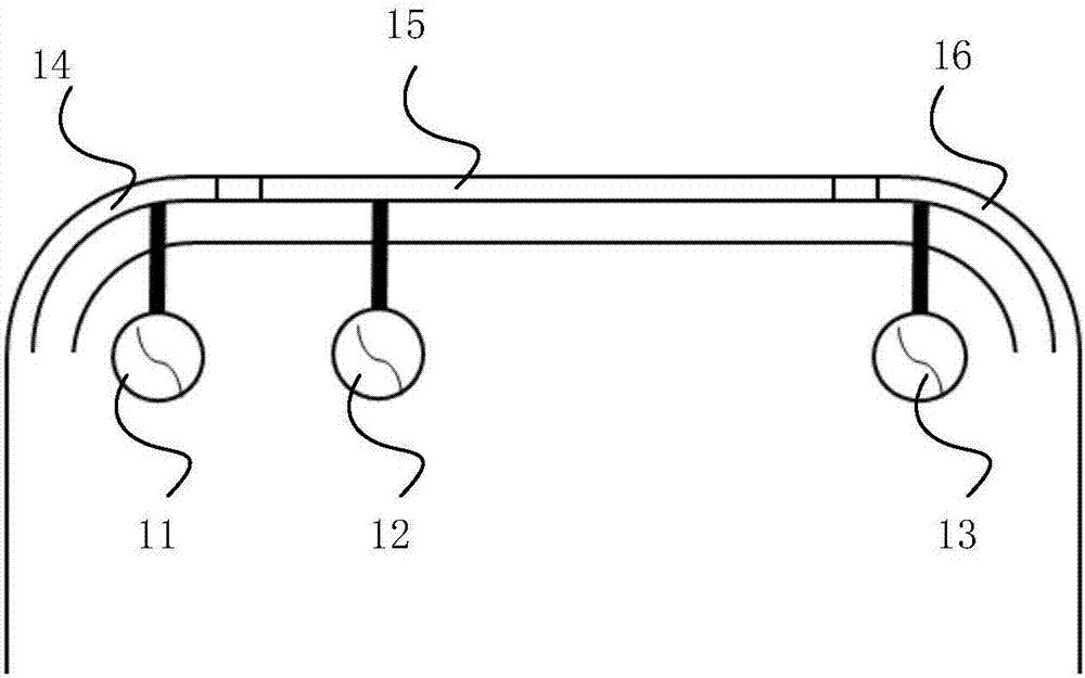
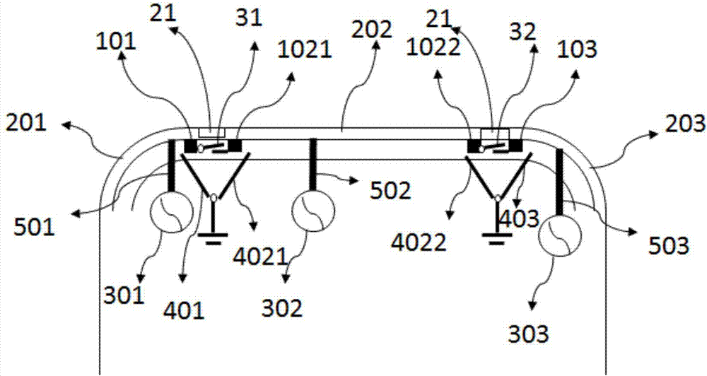
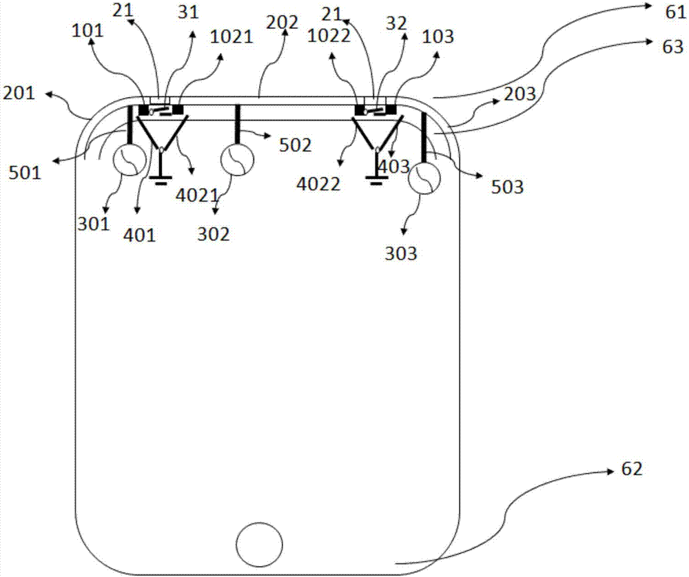
[0018] refer to figure 2 , showing a schematic diagram of an antenna device according to an embodiment of the present invention, which is applied to a mobile terminal, and the device specifically includes:

[0019] at least two antenna assemblies, 3 antenna assemblies are shown here,

[0020] Each antenna assembly includes: a radiator and a feeding source, the radiator and the feeding source are electrically connected to each other, and the feeding s...


PUM


Abstract

The present invention provides an antenna device and a mobile terminal. The device includes: at least two antenna assemblies, each antenna assembly includes: a radiator and a feeder, the radiator and the feeder are electrically connected to each other, and the feeder is used to feed electrical signals to the radiator; They are isolated from each other, and there are isolation ports between the radiators of different antenna assemblies; each antenna assembly also includes at least one first switch, wherein one end of each first switch is connected to the ground point, and the other end is selected from the radiating end of the radiator The radiating end is one end of the radiator located at the isolated port, and each first switch is used to control whether the radiating end of each radiator is connected to the grounding point. In the present invention, each antenna assembly is provided with a grounding switch selectively electrically connected to the radiating end of the radiator, so that at least one radiating end of the antenna assembly can be grounded flexibly, thereby increasing the isolation between at least two antenna assemblies .

Description

technical field [0001] The present invention relates to the technical field of communications, in particular to an antenna device and a mobile terminal. Background technique [0002] At present, the antenna of the mobile communication device is in the form of a metal frame. Since the metal frame needs to be disconnected, the metal frame is divided into multiple parts, and each part has different lengths, forming antenna radiators of different frequency bands. In the existing technology, such as figure 1 As shown, the antenna is connected to the middle frame of the antenna through the feeder 11, the feeder 12 or the feeder 13, etc., and the mid-high frequency antenna radiator 14, the low mid-high frequency antenna radiator 15, and the mid-high frequency antenna radiator 16 are formed in the middle frame. Wait. [0003] However, if figure 1 As shown, the installation positions of the medium-high frequency antenna radiator 14 for transmitting and receiving medium-high freque...

Claims


Application Information

Patent Timeline
Patent Type & Authority Applications(China)
IPC IPC(8): H01Q1/36H01Q1/24H01Q1/50
CPCH01Q1/36H01Q1/243H01Q1/50
Inventor 付堉皓
Owner VIVO MOBILE COMM CO LTD
Why Eureka
Try Eureka