Light emitting structure and clock with same

A light-emitting structure and clock technology, which is applied to semiconductor devices of light-emitting elements, mechanically driven clocks, clocks, etc., can solve the problems of increasing the light and shadow arrangement and fun of the home environment, and unclear light and shadow projection, so as to reduce the poor projection effect, The effect of reducing the size of the area

Inactive Publication Date: 2017-10-03
LIQ MENG CORP
View PDF4 Cites 0 Cited by
  • Summary
  • Abstract
  • Description
  • Claims
  • Application Information

AI Technical Summary

Problems solved by technology

[0005] In view of the problem of unclear light and shadow projection in the existing light-emitting structures, at this stage there is a need for a light spot that can clearly project each light source on the wall surface, making it easy to be identified by the viewer, and through the light-transmitting plate The structural design of the light source makes the light intensity of the light emitted by the light source not weaken sharply through the light-transmitting plate, effectively maintaining the intensity of the light, so that the light spot can be projected on the wall surface more clearly, increasing the light and shadow of the home environment Setup and Fun

Method used


Image

  • Light emitting structure and clock with same
  • Light emitting structure and clock with same
  • Light emitting structure and clock with same

Examples


Embodiment Construction

[0025] In the following, the technical means adopted by the present invention to achieve the intended purpose of the invention will be further described in conjunction with the drawings and preferred embodiments of the present invention.

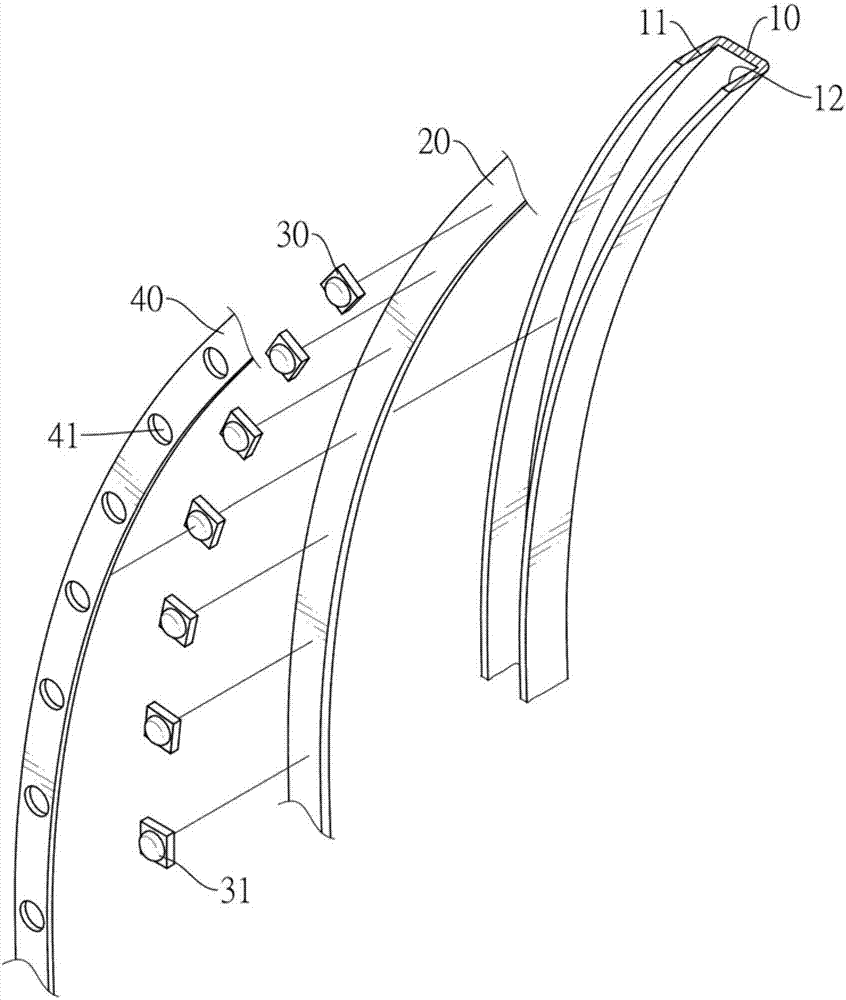
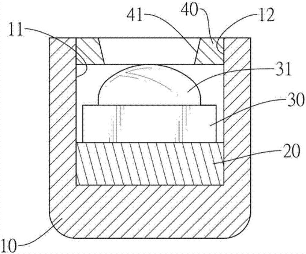
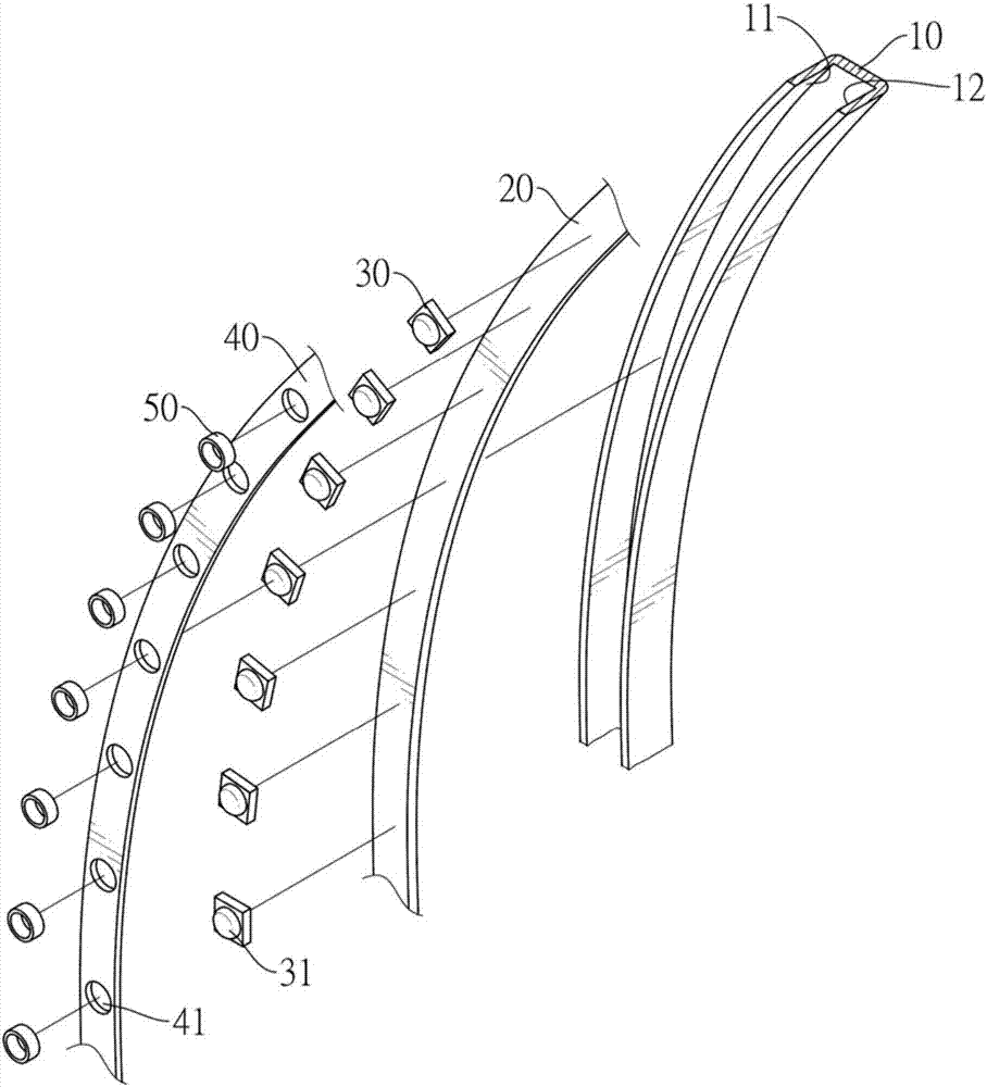
[0026] Such as figure 1 and figure 2 As shown, the light emitting structure of the first embodiment of the present invention includes: a frame body 10 , a circuit board 20 , a plurality of light emitting sources and a light guide cover 40 .

[0027] The frame body 10 has a groove 11 , the groove 11 has a concave-shaped cross section in side view, and an opening 12 is formed at the top of the groove 11 .

[0028] The circuit board 20 is mounted in the groove 11 of the frame body 10, and can be selectively attached to the inner surface of the groove 11; On the circuit board 20, and the light sources 31 of the light emitting diodes 30 are respectively arranged towards the opening 12 of the frame body 10, after the light emitting diodes 30 ar...


PUM


Abstract

The invention relates to a light emitting structure and a clock with the same. A circuit device and light emitting sources are accommodated in a frame of the light emitting structure; a plurality of light guide holes corresponding to positions of the light emitting sources are formed in a light guide casing covering the frame so as to help the light emitting source to irradiate light to an outer part of the frame via the light guide holes, and light spots can be projected on a wall surface for shadow arrangement of a household environment or time indicating of the clock.

Description

technical field [0001] The present invention is a light-emitting structure and a clock with the light-emitting structure, especially a light-emitting structure and a clock with a light projection function, which can clearly project the light points of each light source on the wall surface, providing a wall surface. A light-emitting structure with surface arrangement or time indication and a clock with the light-emitting structure. Background technique [0002] The light-emitting structure of the general household products nowadays is to use the light-emitting source and the circuit board to be arranged in the frame body with at least one opening, and then use a transparent light-transmitting plate to cover the opening of the frame body, so that the light-emitting source is energized and emitted. The light can pass through the transparent light-transmitting plate and irradiate towards the outside of the frame. [0003] However, since the light source generally irradiates out...

Claims


Application Information

Patent Timeline
Patent Type & Authority Applications(China)
IPC IPC(8): F21S8/00F21V3/02F21V19/00F21V23/00F21V33/00F21Y115/10
CPCG04B19/30F21V33/0004F21Y2103/33F21Y2115/10F21S8/00F21V3/02F21V19/001F21V23/00F21V33/0024
Inventor 尹庆坤
Owner LIQ MENG CORP
Why Eureka
Try Eureka