A Method for Lossless Switching of System Clock

A system clock and clock switching technology, applied in the field of communication, can solve the problems of clock switching instability, interruption, communication network packet loss, etc., and achieve the effect of overcoming the interlocking clock delay

Active Publication Date: 2020-01-07
OPHYLINK COMM TECH
View PDF4 Cites 0 Cited by
  • Summary
  • Abstract
  • Description
  • Claims
  • Application Information

AI Technical Summary

Problems solved by technology

[0003] The purpose of the present invention is to provide a method for lossless switching of the system clock, which is used to solve the problem of packet loss or even interruption in the communication network due to the instability of the clock switching when the control card in the communication device in the prior art performs active / standby switching. question

Method used


Image

  • A Method for Lossless Switching of System Clock
  • A Method for Lossless Switching of System Clock
  • A Method for Lossless Switching of System Clock

Examples


Embodiment 1

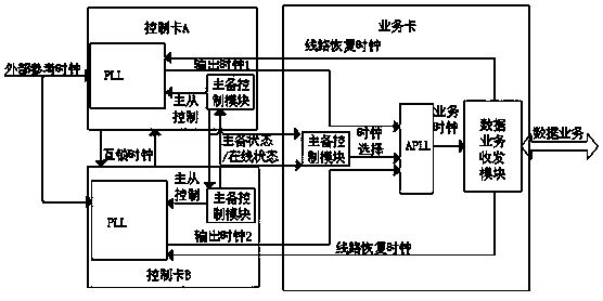
[0036] combined with figure 1 and figure 2 As shown, a method for lossless switching of a system clock includes the following steps:

[0037] S1) Initialize the control card A, control card B and service card on the communication device: control card A is set as the main controller, the clock mode is set as the main mode, the control card B is set as the backup controller, and the clock mode is set as In the slave mode, the clock of the service card tracks the clock of the control card A, and both the control card A and the control card B include:

[0038] Master-standby control module: used to detect the master-standby switchover status of each module and monitor the master-standby switchover trigger signal;

[0039] Phase-locked loop PLL: including a digital phase-locked loop DPLL and an analog phase-locked loop APLL, the digital phase-locked loop DPLL works in the master mode, and the analog phase-locked loop APLL works in the slave mode;

[0040] Interlock clock: used ...

Embodiment 2

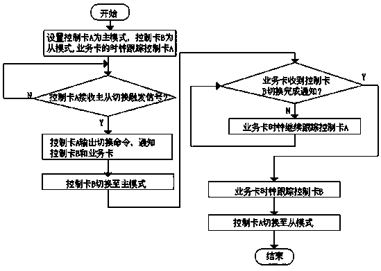
[0049] On the basis of Example 1, in conjunction with the attached figure 1 and figure 2 As shown, the clock of the control card A in S1) is an external reference clock or a line recovery clock, and the clock of the control card B tracks the interlock clock.

[0050] When the clock of control card A is an external reference clock, when the controller card B switches from the slave mode to the master mode, the tracked clock is switched from the clock of control card A to the external reference clock or line recovery of the same source as the clock of control card A clock. Therefore, although the control card A and the control card B are both in the main mode at this time, since the clocks are from the same source, the data services of the service cards will not be lost or interrupted.

[0051] Preferably, preferably, the specific content of the step S3) switching from the slave mode to the master mode is: the control card B switches from the analog phase-locked loop APLL to ...

Embodiment 3

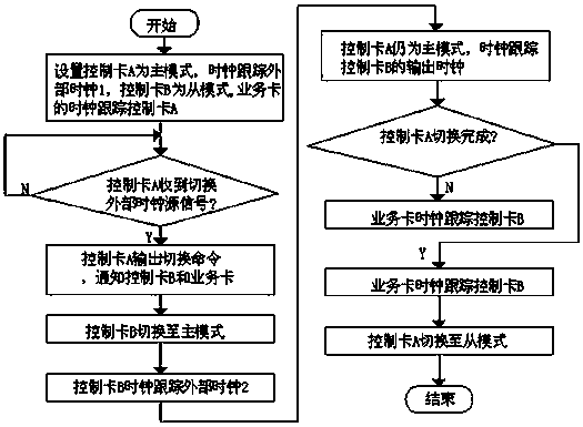
[0054] On the basis of Example 1, in conjunction with the attached Figure 1-3 As shown, when the clock of control card A in S1) is set to external reference clock 1, the clock of control card B is set to external reference clock 2 and the active and standby control modules of control card A in S2) monitor the external reference clock switch trigger signal when the

[0055] The above S3) is replaced by: M1) After the control card B receives the switching command from the control card A, the active and standby control modules of the control card B will switch the working state of the phase-locked loop PLL, and the clock mode will be switched from the slave mode to the master mode , the clock of the control card B tracks the external reference clock 2, and the output clock of the control card B is synchronized with the external reference clock 2;

[0056] The above S4) is replaced by: M2) The clock mode of the control card A is still the main mode, the clock of the control card...


PUM


Abstract

The invention discloses a method for lossless switching of a system clock. The method includes the steps that (1) a control card A, a control card B and a service card are initialized, wherein the clock mode of the control card A is set as a main mode, and the clock mode of the control card B is set as a slave mode; (2) a main standby control module of the control card A monitors a main standby switch trigger signal, and sends a switching command to the control card B and the service card; (3) after the control card B receives the switching command, the clock mode is switched from the slave mode to the main mode; (4) the control card B completes switching of the clock mode and informs the service card; (5) after the service card receives the information from the control card B, the clock of the service card tracks the clock of the control card B; (6) the clock mode of the control card A is switched from the main mode to the slave mode. The method for lossless switching of the system clock uses the main standby control module of the board cards, and overcomes the disadvantages of interlocking clock delay in the process of clock switching, clock loss because the board cards are pulled out, and service interruption because a non-synchronization clock source conducts clock switching.

Description

technical field [0001] The invention relates to the technical field of communication, in particular to a method for lossless switching of system clocks. Background technique [0002] In the prior art, a communication device is composed of various boards, such as a power supply card, a control card, a service card, a fan card, and the like. In order to improve the reliability and stability of the system, 1+1 backup is adopted for some core function boards, for example, the backup function is made for the control card. When the main control card fails or is manually switched, it can automatically switch to the standby control card. During the master / standby switchover process, the clock source of the service card will also be switched accordingly. In the current clock master-standby switching scheme, the master control card uses a digital phase-locked loop to track the reference source, and generates multiple synchronous clocks, which are sent to the service card. At the sa...

Claims


Application Information

Patent Timeline
Patent Type & Authority Patents(China)
IPC IPC(8): G06F1/10
CPCG06F1/10
Inventor 凌烽
Owner OPHYLINK COMM TECH
Why Eureka
Try Eureka