Vehicle-mounted screen rotating structure

A technology of screen rotation and screen, applied in vehicle parts, transportation and packaging, etc., can solve the problems of inconvenient processing and molding, inconvenient installation, complex structure, etc., and achieve the effect of convenient processing, convenient disassembly and assembly, and long service life

Active Publication Date: 2017-10-10
FORYOU MULTIMEDIA ELECTRONICS
View PDF6 Cites 6 Cited by
  • Summary
  • Abstract
  • Description
  • Claims
  • Application Information

AI Technical Summary

Problems solved by technology

[0003] However, the vehicle-mounted screen rotation system in the prior art often has problems such as complex structure, inconvenient installation, short life, and inconvenient processing and molding

Method used


Image

  • Vehicle-mounted screen rotating structure
  • Vehicle-mounted screen rotating structure
  • Vehicle-mounted screen rotating structure

Examples


Embodiment 1

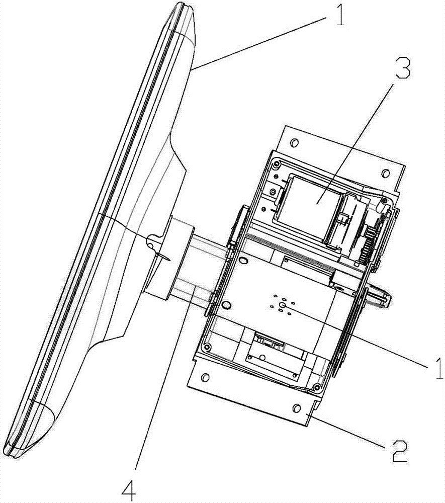
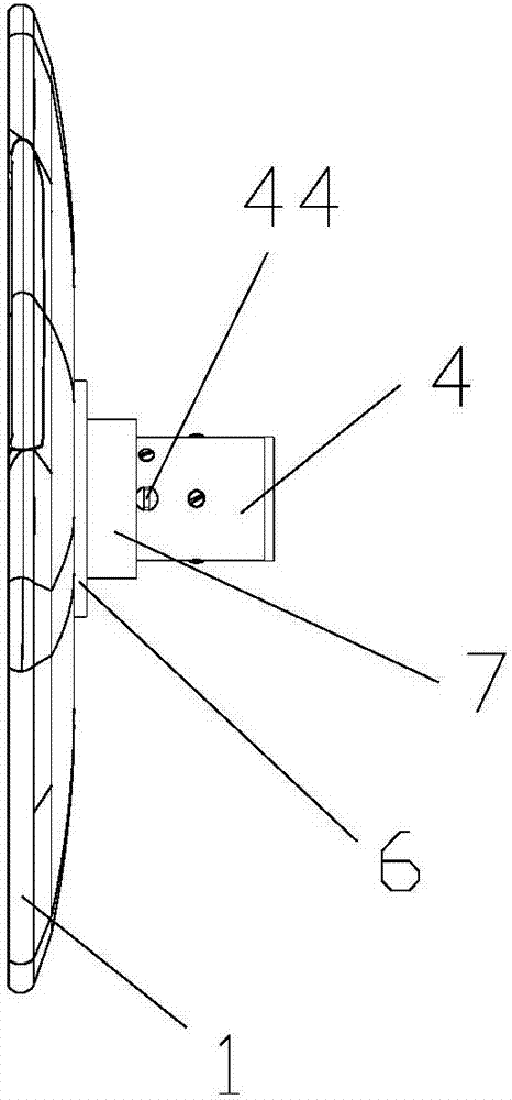
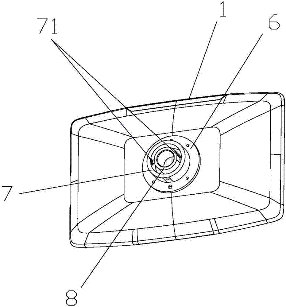
[0026] Such as figure 1 , figure 2 , image 3 , Figure 4 As shown, this embodiment discloses a vehicle-mounted screen rotation structure, including a screen 1, a base 2, a driving motor 3, a rotating shaft 4, and a transmission shaft 5; the driving motor 3 and the rotating shaft 4 are respectively arranged on the base 2; the transmission shaft 5 The rotating shaft 4 is driven to rotate by the drive motor 3; an L-shaped slot 41 is provided on the outer surface of the rotating shaft 4; a screen pressing block 42 is arranged in the rotating shaft 4; an energy storage part is arranged on the screen pressing block 42 43; A limiting part 44 for pre-pressing the screen pressing block is provided on the rotating shaft 4. The specific limiting part 44 can be a limiting pin, and a hole is opened on the rotating shaft 4 for the limiting pin 4 to be inserted into the rotating shaft 4. Limiting hole, so that the limit pin can be inserted into the inside of the rotating shaft 4 to pre-...

Embodiment 2

[0030] Such as Figure 5 , Image 6 As shown, as a further technical solution, the difference between this embodiment and Embodiment 1 is that an arc-shaped track groove 45 is also provided on the rotating shaft 4; one end of the transmission shaft 5 is installed on the drive motor 3, and the other end is installed In the arc track groove 45 on the rotating shaft 4 , driven by the driving motor 3 , the rotating shaft 4 is driven to rotate. Simultaneously, a shaft sleeve 9 is sleeved on the transmission shaft 5, and its function is to make the shaft sleeve 9 contact with the arc-shaped track groove 45 on the rotating shaft 4, and drive the rotating shaft 4 to rotate through rolling friction to reduce frictional force.

[0031] Specifically, when designing, the initial end and the terminal end of the arc track groove 45 can use a straight line parallel to the direction of motion of the transmission shaft 5, so as to realize the self-locking of the two positions; meanwhile, the ...


PUM


Abstract

The invention relates to the technical field of vehicle-mounted display devices, in particular to a vehicle-mounted screen rotating structure. The vehicle-mounted screen rotating structure comprises a screen, a base, a driving motor, a rotating shaft and a transmission shaft; the driving motor and the rotating shaft are arranged on the base; the transmission shaft drives the rotating shaft to rotate through the driving motor; L-shaped clamping grooves are formed in the outer side face of the rotating shaft; a screen pressing block is arranged in the rotating shaft; an energy storage part is arranged on the screen pressing block; a flange plate is arranged on the back face of the screen; an outer shaft sleeve and an inner shaft sleeve are arranged on the flange plate; the outer shaft sleeve is used for being installed outside the rotating shaft, the inner shaft sleeve is used for being installed inside the rotating shaft, and clamping blocks matched with the L-shaped clamping grooves in the rotating shaft are arranged on the inner wall of the outer shaft sleeve. By means of the technical scheme, screw-free connection between the screen and a rotating mechanism can be achieved, disassembling and assembling are convenient, the service life is long, and machining is convenient; meanwhile, screen rotating self-locking and collapsing can be achieved, the structure is simple, and use is convenient.

Description

technical field [0001] The invention relates to the technical field of vehicle-mounted display devices, in particular to a vehicle-mounted screen rotation structure. Background technique [0002] With the development of science and technology, electronic products have been widely promoted and applied, and the use of display screens in cars is becoming more and more common. There are two main types of car monitors. One is the TV placed on the bus, which is essentially a car monitor. TV, the other is a small size car monitor with 3.5 inches, 4.3 inches, 7 inches and 9 inches. Generally, there are two video inputs, one can be connected to the car DVD, and the other is used to connect the reversing image car camera. With MP5 video playback and bluetooth function, the display that can be used on similar sports tools in automobiles is convenient to use in automobile sports. At present, in order to facilitate the installation and fixing of vehicle display screens, the installation ...

Claims


Application Information

Patent Timeline
Patent Type & Authority Applications(China)
IPC IPC(8): B60R11/02
CPCB60R11/0229
Inventor 卢盘游云兵王奎黄秀煜全云龙李振翔
Owner FORYOU MULTIMEDIA ELECTRONICS
Why Eureka
Try Eureka