
a sunshade device

A technology of sunshade device and sunshade, applied in the direction of sunshade, construction, building structure, etc., can solve the problems of unsuitability for popularization, poor sunshade effect, economic loss, etc. Effect

Active Publication Date: 2019-03-15
深圳市安百纳科技有限公司
View PDF5 Cites 0 Cited by
  • Summary
  • Abstract
  • Description
  • Claims
  • Application Information

AI Technical Summary

Problems solved by technology

[0002] Sunshade devices used to block the sun can often be seen in front of some shops. Traditional sunshade devices are generally designed in one piece and cannot be stretched. The damage will cause serious losses to people's economy. At the same time, due to the continuous changes in the angle of sunlight during the day, the traditional sunshade device does not have the function of angle adjustment, so the sunshade effect is poor and there are major disadvantages. Although there are many sunshade devices that can adjust the sunshade angle by themselves in the prior art, their prices are relatively expensive and the operation is relatively cumbersome, so they are not suitable for popularization and use.

Method used


Image

  • a sunshade device
  • a sunshade device
  • a sunshade device

Examples


Embodiment Construction

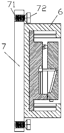
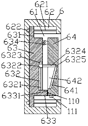
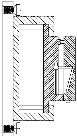
[0020] Such as Figure 1-Figure 5 As shown, a sunshade device of the present invention includes a base body 6, and a fixing plate 7 arranged on the left end face of the base body 6, and the right end face of the fixing plate 7 is fixedly arranged on the left end face of the base body 6. , the four corners of the fixing plate 7 are respectively provided with fixing holes 71, the fixing holes 71 are provided with fixing bolts 72, the base body 6 is provided with a cavity 61, and the right side of the cavity 61 is provided with In the mouth, the upper and lower inner walls of the cavity 61 are symmetrically provided with first sliding grooves 62, and each of the first sliding grooves 62 is provided with a first screw rod 621, and the left end side of the first screw rod 621 is connected to the first The motor 622 is connected, and a slide frame 63 is provided in the cavity 61, and limit blocks 631 are arranged on the upper and lower sides of the slide frame 63, and a sun visor 64...


PUM


Abstract

The invention discloses a novel sun shading device comprising a base body and a fixing plate arranged on the left side end face of the base body. The right side end face of the fixing plate and the left side end face of the base body are fixedly arranged; fixing holes are formed in the four corners of the fixing plate correspondingly; fixing bolts are arranged in the fixing holes; a containing cavity is formed in the base body; an opening part is arranged on the right side of the containing cavity; first sliding grooves are symmetrically formed in the upper inner wall and the lower inner wall of the containing cavity; each first sliding groove is internally provided with a first screw rod; the left end sides of the first screw rods are connected with first motors; a sliding frame is arranged in the containing cavity; limiting blocks are symmetrically arranged on the upper side and the lower side of the sliding frame; a sun shading plate is arranged on the right side of the sliding frame; the upper end of the right side of the sliding frame and the upper end of the left side of the sun shading plate are connected in a matched mode through a movable piece; and an abutting block is arranged at the edge of the bottom of the right side of the sliding frame. According to the novel sun shading device, the structure is simple, operation is convenient, multiple-angle adjustment can be achieved, the sun shading effect is good, the protective function is achieved, and the service life is long.

Description

technical field [0001] The invention relates to the technical field of sunshade devices, in particular to a sunshade device. Background technique [0002] Sunshade devices used to block the sun can often be seen in front of some shops. Traditional sunshade devices are generally designed in one piece and cannot be stretched. The damage will cause serious losses to people's economy. At the same time, due to the continuous changes in the angle of sunlight during the day, the traditional sunshade device does not have the function of angle adjustment, so the sunshade effect is poor and there are major disadvantages. Although there are also more sunshade devices that can adjust the sunshade angle voluntarily in the prior art, their prices are relatively expensive, and the operation is comparatively loaded down with trivial details, so it is not suitable for popularization and use. Contents of the invention [0003] The technical problem to be solved by the present invention is ...

Claims


Application Information

Patent Timeline
Patent Type & Authority Patents(China)
IPC IPC(8): E04F10/00
CPCE04F10/00
Inventor 沈奇
Owner 深圳市安百纳科技有限公司
Learn More