Refrigerator

A refrigerator and wiring technology, applied in the field of refrigerators, can solve problems such as the cost of holes for hinges

Active Publication Date: 2017-10-10
MITSUBISHI ELECTRIC CORP
View PDF10 Cites 4 Cited by
  • Summary
  • Abstract
  • Description
  • Claims
  • Application Information

AI Technical Summary

Problems solved by technology

In this way, there is a problem that modification such as enlarging the hole of the hinge is required, and the cost for modifying the hole of the hinge is spent every time electronic parts are added.

Method used


Image

  • Refrigerator
  • Refrigerator
  • Refrigerator

Examples


Embodiment approach

[0021] [Structure of Refrigerator 100]

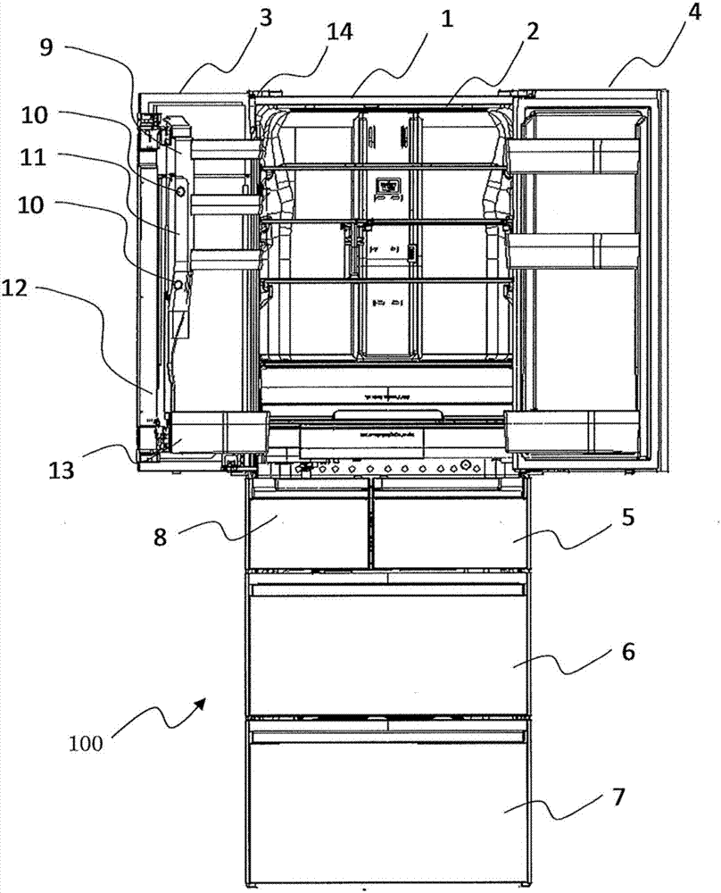
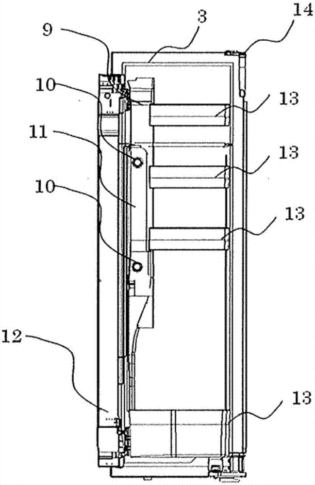
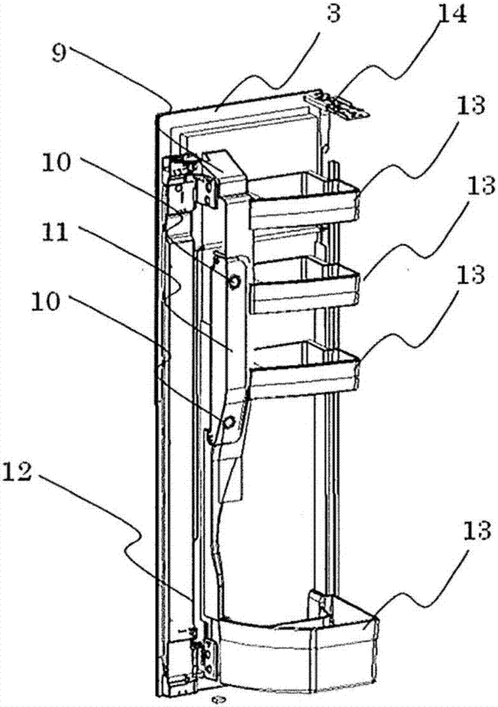
[0022] figure 1 It is a schematic front view of the refrigerator which concerns on embodiment of this invention. 2( a ) and FIG. 2( b ) are schematic diagrams of the left door of the refrigerator compartment of the refrigerator according to the embodiment of the present invention. Such as figure 1 As shown, the refrigerator main body 1 has a refrigerator compartment 2 with an open front surface at the uppermost part, and on the front surface side of the refrigerator compartment 2, a side-by-side refrigerator compartment left door 3 that closes the opening in an openable and closable manner and a refrigerator compartment are provided. Right door 4. Refrigerator compartment left door 3 is openably and closably attached to the refrigerator main body via hinge 14 . In addition, ice making compartment 8 is provided below the left side of refrigerating room 2 , and switching room 5 is provided below the right side of refrigerating room 2 ...


PUM


Abstract

This refrigerator comprises: a refrigerator body; a storage chamber which is formed in the refrigerator body and has a front opening; a door which openably closes the front opening of the storage chamber; a plurality of electric components which are installed on the inner surface or the inside of the door; a sub-control unit which is installed on the door, is connected to the plurality of electric components through individual wires, and converts the individual wires to a common wire; and a main control unit which is provided in the refrigerator body, is connected to the sub-control unit through the common wire, and controls the plurality of electric components.

Description

technical field [0001] The present invention relates to a refrigerator in which a wiring material is arranged via a hinge of a door. Background technique [0002] Conventionally, there has been proposed a refrigerator in which a wiring material is provided through a hole provided in a door hinge, and the wiring material is used to connect electronic components provided on the door of the refrigerator to a main control unit on the side of the refrigerator main body (for example, refer to Patent No. Literature 1). [0003] Patent Document 1: Japanese Patent Laid-Open No. 2002-340472 [0004] In the refrigerator described in Patent Document 1, when a plurality of electronic components such as an imaging unit are installed on the door of the storage room, the number of wiring materials increases by the amount corresponding to the number of electronic components. Therefore, when the wiring material is to be connected to the main control unit provided in the main body of the ref...

Claims


Application Information

Patent Timeline
IPC IPC(8): F25D11/02F25D29/00
CPCF25D11/02F25D29/003F25D23/00
Inventor 笹原骏介
Owner MITSUBISHI ELECTRIC CORP
Why Eureka
Try Eureka