Liquid ejecting apparatus and method of controlling same

A spraying device and liquid technology, applied in the direction of inking device, printing, etc., can solve the problem of enlargement and achieve the effect of reducing the quantity

Inactive Publication Date: 2008-10-15
SONY CORP
View PDF1 Cites 4 Cited by
  • Summary
  • Abstract
  • Description
  • Claims
  • Application Information

AI Technical Summary

Problems solved by technology

Therefore, there arises a problem that the area of ​​the motherboard on which the central processing unit 4 and the like are arranged becomes enlarged, and the configuration area where the motherboard is connected to the printer becomes enlarged

Method used


Image

  • Liquid ejecting apparatus and method of controlling same
  • Liquid ejecting apparatus and method of controlling same
  • Liquid ejecting apparatus and method of controlling same

Examples


no. 1 example

[0022] (1) Configuration of this embodiment

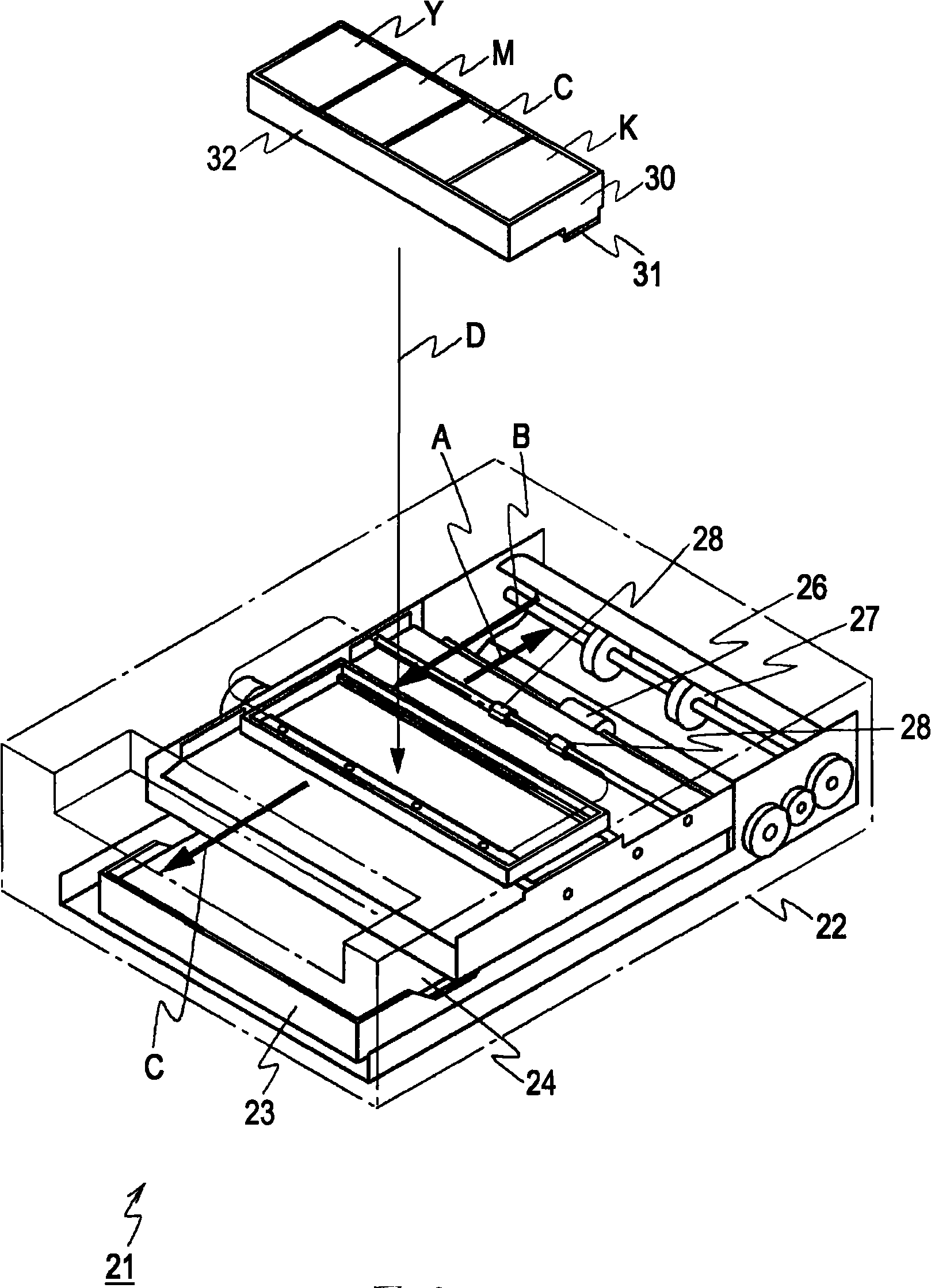
[0023] figure 2 is a perspective view showing the printer 21 according to the first embodiment of the present invention. The printer 21 is a line printer. It is integrally formed in such a manner as to be equipped in a rectangular housing 22 , and a paper tray 23 equipped with printing paper 24 is installed from a slot-type inlet formed in the front side of the housing 22 .

[0024] Here, when the paper slot 23 is installed in the printer 21, a predetermined mechanism causes the printing paper 24 to be pressed by the paper conveying roller 26, and due to the rotation of the paper conveying roller 26, the printing paper 24 is conveyed toward the side opposite to the paper slot 23, as indicated by an arrow. Indicated by A. In the printer 21, the reverse roller 27 is disposed on the side where the paper is conveyed, and due to the rotation of the reverse roller 27, the conveying direction of the printing paper 24 is shifted to the ...


PUM


Abstract

A liquid ejecting apparatus for ejecting droplets by driving heat generating elements includes an electrical current source configured to output temperature measurement current; a plurality of head chips, each having a heat generating element, a temperature sensor whose resistance value changes with temperature, a switch circuit that connects the temperature sensor to the electrical current source, and a switch-circuit control circuit configured to control the switch circuit; and a heat-generating-element control circuit configured to measure temperatures of the plurality of head chips and controlling the driving of the heat generating elements via an end of the electrical current source on the temperature sensor side.; The temperature sensors of the plurality of head chips are sequentially and selectively connected to the electrical current source by the switch circuits of the plurality of head chips, and the temperatures of the plurality of head chips are measured by the heat-generating-element control circuit.

Description

technical field [0001] The present invention relates to a liquid ejecting device and a method of controlling the same, and can be applied, for example, to a thermal line printer. In the present invention, a current source for measuring temperature is shared among a plurality of head chips, a temperature sensor of each head chip is sequentially and optionally connected to the current source, and each head chip is measured at an end on the current source side. The temperature of each magnetic head chip, so that the configuration of temperature measurement is miniaturized compared with the related art. Background technique [0002] In the related art, in a thermal printer as a liquid ejecting device, a heat generating element provided in a head chip of the thermal printer is driven to eject ink droplets. Here, the head chip is a semiconductor substrate and is constructed by a semiconductor manufacturing process on which a plurality of heat generating elements, a driving circui...

Claims


Application Information

Patent Timeline
Patent Type & Authority Applications(China)
IPC IPC(8): B41J2/05B41J2/355B41J2/14
CPCB41J2/1752B41J2/04563B41J2/0458B41J2202/19B41J2/045B41J2/04541B41J2/05B41J2/1404B41J2/14072B41J2/14145
Inventor 牛浜五轮男
Owner SONY CORP
Why Eureka
Try Eureka