Light Source Module

Active Publication Date: 2014-12-18
AU OPTRONICS CORP
View PDF2 Cites 5 Cited by
  • Summary
  • Abstract
  • Description
  • Claims
  • Application Information

AI Technical Summary

Benefits of technology

[0012]Compared to the prior arts, the light source module of the present invention modifies the pin arrangement of adjacent light source units, so that the pins having the same polarity is adjacently disposed to decrease the amount of the conducting wires so as to decrease the layout area between the light source units, further shortening the spacing between the first light source unit and the second light source unit. In practical applications, the light source module is a circuit board having a single strip of light bar, and the cost of the materials is cheap so as to save the cost. In practical applications, if the width of the light source unit is 3.8 mm, the prior art of

Problems solved by technology

The wire space width L is a major factor to influence the magnitude of the pitch P. However, in the present design structure, it is difficult to decrease the width of the conducting wire 8 and the spacing between adjacent conducting wires, so that the pitch P is difficult to be decreased.
Particularly, in the case that the substrate 3 has a given ar

Method used


Image

  • Light Source Module
  • Light Source Module
  • Light Source Module

Examples


Embodiment Construction

[0024]According to an embodiment of the present invention, a light source module is provided to increase the density of the light source units. In the embodiment, the light source module can be a light source module for display devices.

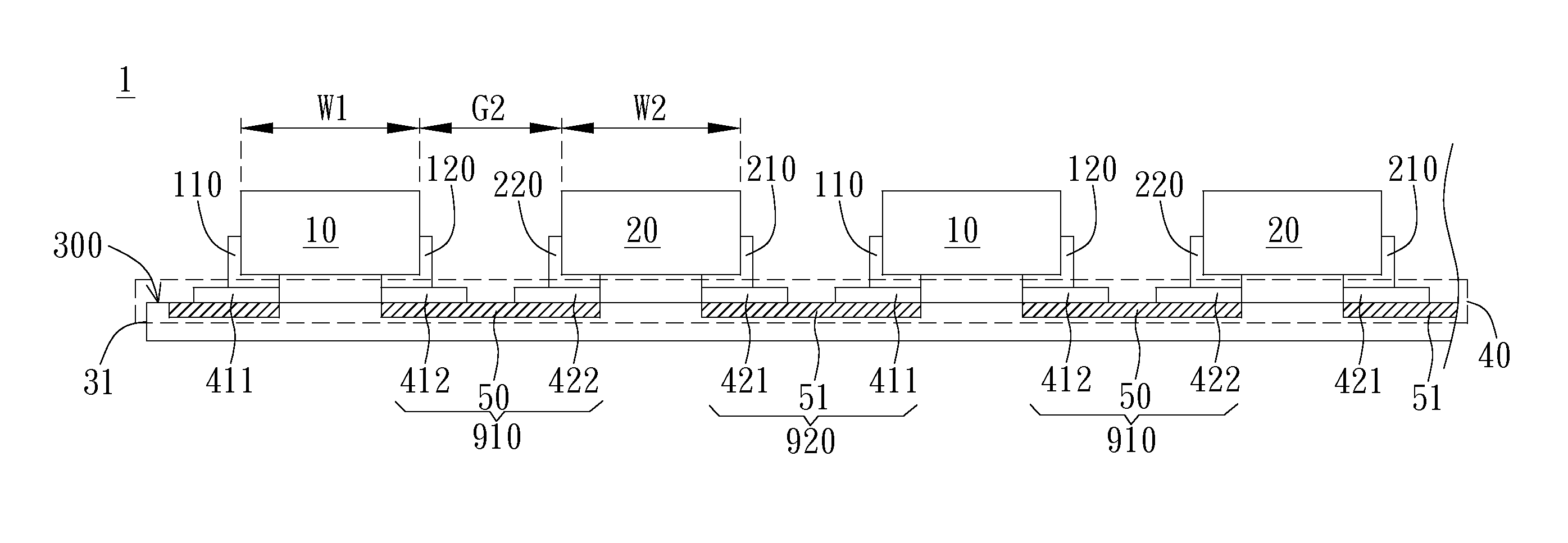
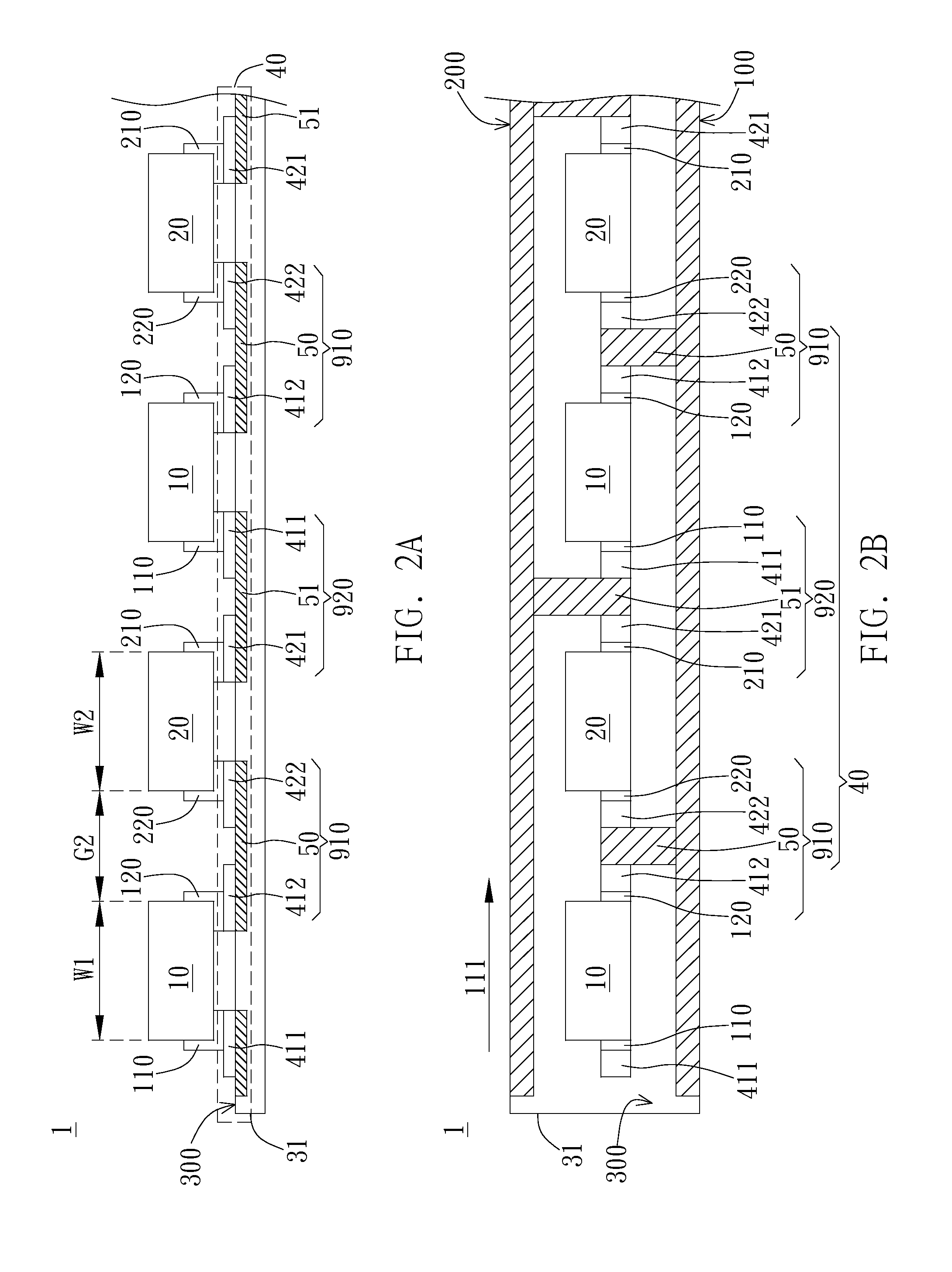
[0025]Please refer to FIG. 2A; FIG. 2A is a side view of an embodiment of a light source module of the present invention. As shown in FIG. 2A, the light source module 1 includes a substrate 31, a circuit 40, at least one first light source unit 10, and at least one second light source unit 20. In the embodiment, the first light source unit 10 and the second light source unit 20 can be LED light sources, but not limited thereto. In addition, the substrate 31 has a bearing surface 300, and the circuit 40 is disposed on the substrate 31 and includes a first signal channel 910 and a second signal channel 920. It is noted that the light source module 1 is a single-layer circuit board; in other words, the substrate 31 of the light source module 1 is a singl...


PUM


Abstract

A light source module includes a substrate, a circuit, at least one first light source unit, and at least one second light source. The circuit is disposed on the substrate and includes a first signal channel and a second signal channel. The first light source unit is disposed on a bearing surface, wherein the first light source unit has a first A pin and a first B pin having different polarity from the first A pin. The second light source unit is disposed on the bearing surface and is adjacent to the first light source unit, wherein the second light source unit has a second A pin and a second B pin having different polarity from the second A pin, and the second A pin is adjacent to the first A pin of the first light source unit and has a same polarity with the first A pin.

Description

BACKGROUND OF THE INVENTION[0001]1. Field of the Invention[0002]The present invention generally relates a light source module; particularly, the present invention relates a light source module which can decrease the cost and increase the brightness.[0003]2. Description of the Prior Art[0004]As shown in FIG. 1, FIG. 1 is a schematic view of a conventional light source module, wherein a light source unit 2A and a light source unit 2B are disposed on a substrate 3. Each of the light source units 2A and 2B has a width W and a spacing G exists between the light source units 2A and 2B. The pitch P of the light source unit 2A and the light source unit 2B is a distance between an edge 21A of the light source unit 2A and an edge 21B of the light source unit 2B. The pitch P can also refer to a sum of the width W and the spacing G. It is noted that the spacing G represents a width allowing the disposition of a layout area between the light source unit 2A and the light source unit 2B. The amoun...

Claims


Application Information

Patent Timeline
IPC IPC(8): F21V23/00
CPCF21V23/00F21Y2115/10H05K1/0296H05K3/3421H05K2201/10106H05K2201/10757
Inventor HSU, MING-JI
Owner AU OPTRONICS CORP
Why Eureka
Try Eureka