
Device and method for improving touch effect of touch control device

A touch position and device technology, applied in the input/output process of data processing, instruments, electrical digital data processing, etc., can solve the problems of inaccurate touch position detection, undetectable touch position, small capacitance value change, etc. To achieve the effect of improving the inaccurate detection and improving the touch effect

Inactive Publication Date: 2017-10-10
CHIPSEA TECH SHENZHEN CO LTD
View PDF15 Cites 0 Cited by
  • Summary
  • Abstract
  • Description
  • Claims
  • Application Information

AI Technical Summary

Problems solved by technology

[0005] When the user's finger is not in good contact with the touch screen, the capacitance value between the touch node and the wire changes very little, even close to 0, resulting in inaccurate detection of the touch position, or even failure to detect the touch position

Method used


Image

  • Device and method for improving touch effect of touch control device

Examples


Embodiment Construction

[0022] In order to make the object, technical solution and advantages of the present invention clearer, the present invention will be further described in detail below in conjunction with the accompanying drawings and embodiments. It should be understood that the specific embodiments described here are only used to explain the present invention, not to limit the present invention.

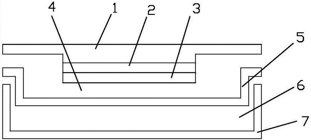
[0023] Referring to the accompanying drawings, it is a device for improving the touch effect of a touch device realized by the present invention. As shown in the figure, the device includes a touch screen 1, a pressure sensor film layer 3, a middle plate 5 and a rear cover 7, and the touch screen 1 The pressure sensor film layer 3 is fixed on the back through the adhesive layer 2; an intermediate plate 5 is arranged on the back of the pressure sensor film layer 3, wherein there is an appropriate safety gap 4 between the pressure sensor film layer 3 and the intermediate plate 5, and the safety gap 4...


PUM


Abstract

The invention discloses a device and method for improving a touch effect of a touch control device. The device comprises a touch screen and a pressure sensor film. The device is characterized in that the pressure sensor film is arranged on the back surface of the touch screen, an intermediate plate is arranged on the back surface of the pressure sensor film, and an appropriate gap which is used for straining pressure is formed between the pressure sensor film and the intermediate plate; meanwhile, the device also has the function that the pressure position is calculated through the pressure sensor film conveniently. According to the device and the method, the problems of inaccurate touch position detection even no output between fingers and the touch screen under the systematic non-good touch state can be solved.

Description

technical field [0001] The invention belongs to the technical field of touch screens, in particular to an electronic device with a touch screen. Background technique [0002] Many electronic devices are now equipped with capacitive touch screens. [0003] The touch technology of the projected capacitive panel The projected capacitive touch screen is to etch different ITO conductive line modules on two layers of ITO conductive glass coating. The patterns etched on the two modules are perpendicular to each other, and they can be regarded as sliders that change continuously in the X and Y directions. Since the X and Y structures are on different surfaces, their intersections form a capacitor node. One slider can be used as a drive line, and the other slider can be used as a sense line. When the current passes through one wire in the drive line, if there is a signal of capacitance change outside, it will cause the change of the capacitance node on the other layer of wire. Th...

Claims


Application Information

Patent Timeline
IPC IPC(8): G06F3/041G06F3/044
CPCG06F3/044G06F3/0418
Inventor 张平
Owner CHIPSEA TECH SHENZHEN CO LTD
Features
  • Generate Ideas
  • Intellectual Property
  • Life Sciences
  • Materials
  • Tech Scout
  • Unparalleled Data Quality
  • Higher Quality Content
  • 60% Fewer Hallucinations
Learn More