Driving circuit for a touch panel realizing modes using a sensing circuit and touch sensing method using the same

a technology of sensing circuit and driving circuit, which is applied in the direction of electric digital data processing, instruments, computing, etc., can solve the problems of increasing the size of the driving circuit and the and achieve the effect of enhancing the use effect of the touch panel and reducing the size and complexity of the driving circui

Active Publication Date: 2020-04-21
IUCF HYU (IND UNIV COOP FOUND HANYANG UNIV)
View PDF11 Cites 2 Cited by
  • Summary
  • Abstract
  • Description
  • Claims
  • Application Information

AI Technical Summary

Benefits of technology

[0010]A driving circuit for a touch panel and a touch sensing method of the invention may operate selectively a mutual capacitance sensing mode and a self capacitance sensing mode using one sensing circuit. Accordingly, a size and a complexity of the driving circuit may reduce, and thus usage effect of the touch panel may be enhanced.

Problems solved by technology

As a result, a size of the driving circuit is increased, and the driving circuit becomes complicated.

Method used


Image

  • Driving circuit for a touch panel realizing modes using a sensing circuit and touch sensing method using the same
  • Driving circuit for a touch panel realizing modes using a sensing circuit and touch sensing method using the same
  • Driving circuit for a touch panel realizing modes using a sensing circuit and touch sensing method using the same

Examples


first embodiment

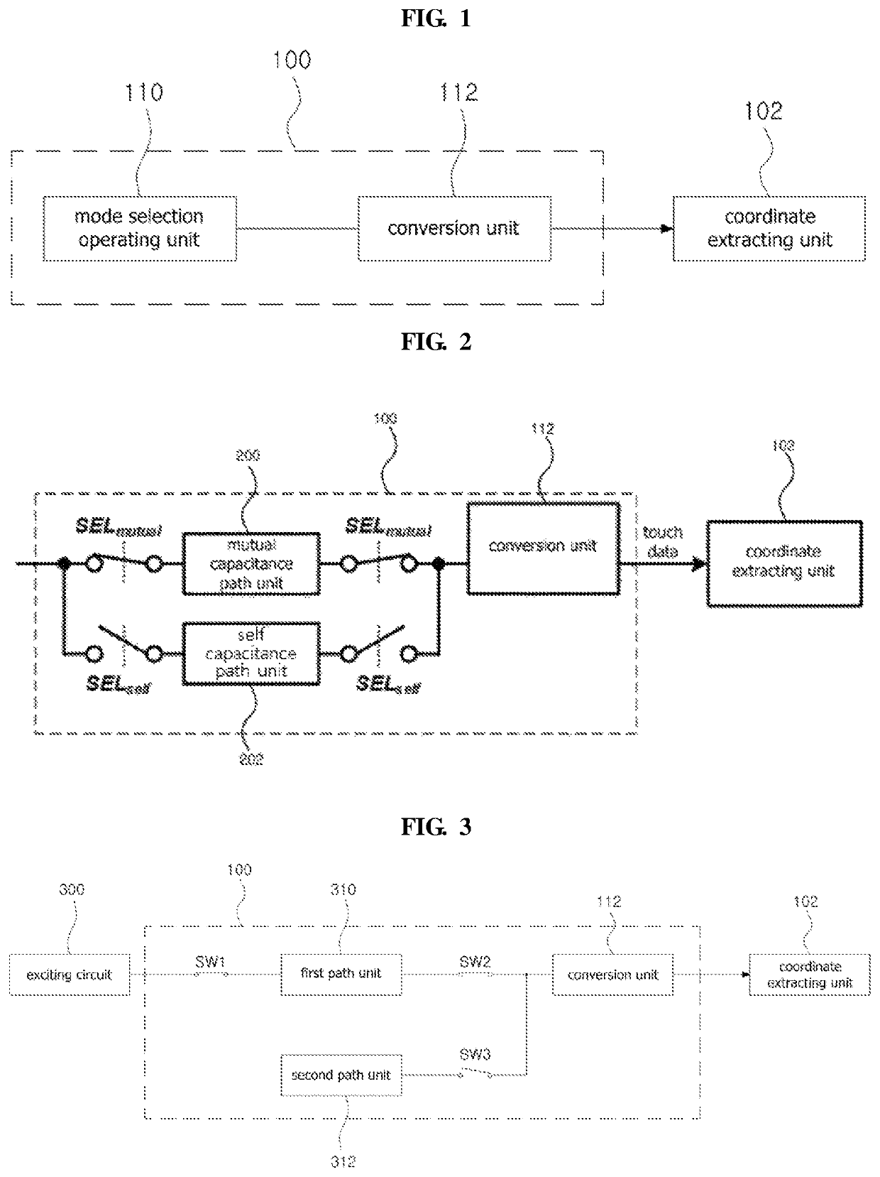
[0041]FIG. 2 is a view illustrating schematically a driving circuit for the touch panel according to the invention.

[0042]In FIG. 2, the mode selection operating unit 110 of the driving circuit includes a mutual capacitance path unit 200, a self capacitance path unit 202 and switches SELmutual and SELself.

[0043]In the mutual capacitance sensing mode, the switches SELmutual are turned on and the switches SELself are off. As a result, the mutual capacitance path unit 200 may sense change of capacitance in response to touch when the touch means touches the touch panel.

[0044]In the self capacitance sensing mode, the switches SELself are tuned on and the switches SELmutual are off. As a result, the self capacitance path unit 202 may sense change of capacitance in response to touch when the touch means touches the touch panel.

[0045]The conversion unit 112 converts the sensed capacitance according to the mode into touch data, and transmits the touch data to the coordinate extracting unit 10...

second embodiment

[0047]FIG. 3 is a view illustrating schematically a driving circuit for a touch panel according to the invention.

[0048]The mode selection operating unit 110 of the driving circuit for the touch panel according to the present embodiment includes a first path unit 310, a second path unit 312 and switches SW1 to SW3. Here, the first path unit 310 may be connected to an excitation circuit 300 through the switch SW1, or be connected to the excitation circuit 300 without the switch SW1. The excitation circuit 300 provides an excitation signal (e.g. pulse) to the first path unit 310.

[0049]In one embodiment, in a first mode, e.g. mutual capacitance sensing mode, the switches SW1 and SW2 are turned on, and the switch SW3 is off. As a result, the first path unit 310 is connected to the excitation unit 300 and the conversion unit 112. The first path unit 310 senses capacitance changed in response to the excitation signal transmitted from the excitation circuit 300 when the touch means touches ...


PUM


Abstract

A driving circuit for a touch panel is disclosed. The driving circuit switches between a mutual capacitance sensing mode and a self capacitance sensing mode using the same sensing circuit. As such, the driving circuit for a touch panel implements a hybrid touch panel that is capable of sensing a touch in either a mutual capacitance sensing mode or a self capacitance sensing mode without requiring a complex and large driving circuit for separate sensing circuits for each mode.

Description

PRIORITY[0001]This application claims priority under 35 U.S.C. § 119(a) to a Korean patent application filed on Dec. 28, 2015 in the Korean Intellectual Property Office and assigned Serial No. 10-2015-0187180 and a PCT application PCT / KR2016 / 015201 filed on Dec. 23, 2016, the entire disclosure of which is incorporated herein by reference.BACKGROUND1. Field of the Invention[0002]The invention relates to a driving circuit for a touch panel capable of operating selectively a mutual capacitance sensing mode or a self conductance sensing mode using one sensing circuit and a touch sensing method using the same.2. Description of the Related Art[0003]A method of sensing touch of a touch panel includes a mutual capacitance sensing method and a self capacitance sensing method.[0004]A conventional driving circuit of a touch panel uses only one of the mutual capacitance sensing method and the self capacitance sensing mode. If the touch panel uses a mutual capacitance sensing mode and a self cap...

Claims


Application Information

Patent Timeline
Patent Type & Authority Patents(United States)
IPC IPC(8): G06F3/041G06F3/044
CPCG06F3/041662G06F3/044G06F3/041
Inventor KWON, OH KYONG
Owner IUCF HYU (IND UNIV COOP FOUND HANYANG UNIV)
Why Eureka
Try Eureka