rotating electrical machine

A technology for rotating electrical machines and rotor cores, applied in electromechanical devices, electrical components, electric components, etc., can solve problems such as increased pressure loss, difficult processing, and increased weight, and achieve stable cooling, easy processing, and high degrees of freedom Effect

Active Publication Date: 2019-03-22
MITSUBISHI ELECTRIC CORP
View PDF5 Cites 0 Cited by
  • Summary
  • Abstract
  • Description
  • Claims
  • Application Information

AI Technical Summary

Problems solved by technology

[0004] However, in the cooling device disclosed in Patent Document 1 above, since the fastening portion between the shaft and the sleeve is communicated from the hole in the core portion of the shaft, and the through hole reaching the outer peripheral surface of the sleeve is provided to form the oil passage of the rotor , therefore, it is difficult to process a radially long hole in a cylindrical member such as a sleeve, and there is a problem that the production cost becomes high.
[0005] In addition, since the oil passage communicated with the fastening part between the shaft and the bushing is provided, there is a possibility that the diameter of the oil passage at the fastening part may deviate due to the dimensional accuracy or assembly accuracy of each component, and there is a possibility that the product The amount of oil in between is not constant, which makes the cooling performance of the rotor deviate.
[0006] In addition, in order to cool the rotor efficiently, it is preferable to cool the permanent magnet as the heat source of the rotor. However, since the oil passage is long, the cooling liquid supplied to the permanent magnet will be after heat exchange with the sleeve and the rotor core. The high-temperature coolant has the problem of insufficient cooling
[0007] In addition, the increase of the oil passage increases the pressure loss. Therefore, in order to ensure the amount of oil required for cooling, the diameter of the oil passage needs to be increased, and there is a problem that the cost and weight increase due to the increase in the size of each part.
[0008] In addition, in the cooling device disclosed in Patent Document 1, the gasket is provided between the rotor cores, and the centrifugal force generated by the rotation of the rotor is used to diffuse the cooling liquid and splash the oil to the stator core to cool the stator as well. , but the output will drop due to the thickness of the gasket, so there is a problem that the motor must be enlarged in order to obtain the necessary output
In addition, the coolant splashed from the rotor enters the gap between the rotor and the stator, and when the rotor rotates, it is sheared and generates heat. Therefore, there is another problem that the coolant becomes a heat source.
[0009] In addition, in rotating electrical machines such as hybrid vehicles and electric vehicles, it is desirable to have high torque in the low-speed rotation region where the fuel efficiency of the engine is poor, but when using the centrifugal force generated by the rotation of the rotor, due to the cooling of the rotor The performance depends on the rotation speed, so there is a problem of insufficient supply of coolant and insufficient output in the low-speed rotation range

Method used


Image

  • rotating electrical machine
  • rotating electrical machine
  • rotating electrical machine

Examples


Embodiment approach 1

[0048] Hereinafter, refer to as Embodiment 1 Figure 1 ~ Figure 3 , to illustrate the present invention.

[0049] In addition, in each figure, the same code|symbol represents the same or a corresponding part.

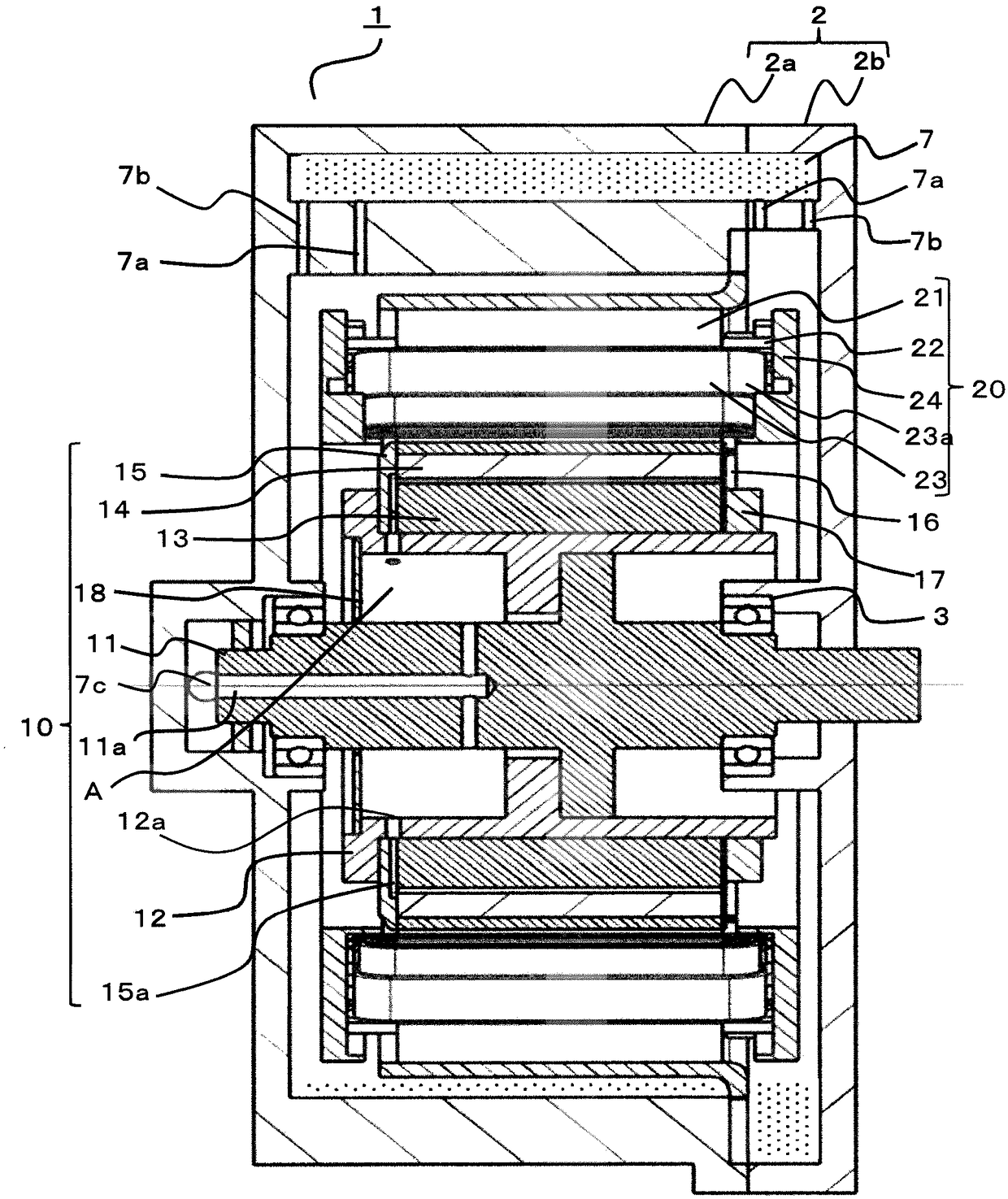
[0050] figure 1 is a cross-sectional view showing a schematic configuration of the rotating electrical machine according to Embodiment 1 of the present invention.

[0051] Such a rotating electrical machine has a function as a motor or a generator, and can be mounted on, for example, a hybrid vehicle or an electric vehicle.

[0052] exist figure 1 Among them, a rotating electrical machine 1 is configured to include: a housing 2 formed by butting a pair of bowl-shaped members 2a and 2b; a stator 20 disposed in the housing 2 in a circumferential shape; and a rotor 10. The rotor 10 and the stator 20 are rotatably disposed on the casing 2 with a certain gap therebetween.

[0053] Here, the stator 20 includes: an annular stator core 21; an insulator 22 assembled to both...

Embodiment approach 2

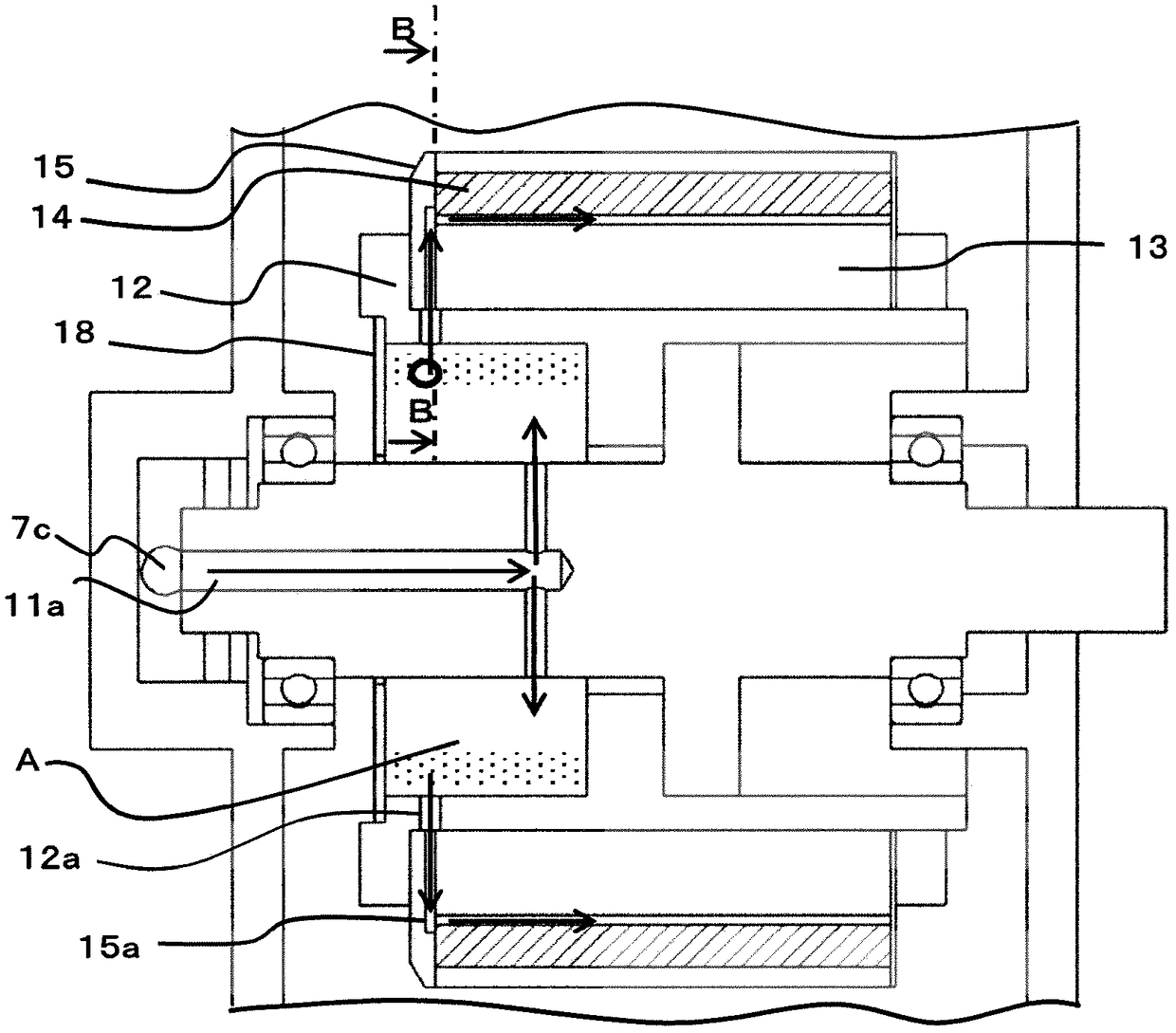
[0070] Figure 5 is a cross-sectional view showing a schematic configuration of a rotating electrical machine according to Embodiment 2 of the present invention.

[0071] In the above-mentioned first embodiment, the guide plate 18 is provided in a substantially disk shape, and the axial end surface of the bearing portion 2c is arranged at a position separated from the boss 12 in the axial direction, but in the second embodiment, as Figure 5 , Image 6 As shown, the guide plate 18 is provided in a substantially cup-shaped shape, and the bearing portion 2c of the housing member 2a supporting the bearing 3 protrudes, and the axial surface 18a of the guide plate 18 is aligned with the shaft sleeve 12. The inner peripheral surface and the outer peripheral surface of the bearing portion 2c face each other with a gap therebetween.

[0072] With the configuration as described above, the coolant released from the through-oil passage hole 11a of the shaft 11 can be accumulated in the...


PUM


Abstract

The present invention relates to a rotary electric machine. (11) which is rotatably supported on the housing (2) for the purpose of achieving efficient cooling by means of a simple method for rotating the coolant into the core for cooling the permanent magnets; a rotor core (13) and a permanent magnet (14) which are mounted on the outer peripheral surface of the sleeve; an end plate (15, 16) And a guide plate (18) which is disposed on the end face of the cylindrical portion of the sleeve and forms a space with the outer peripheral portion of the shaft and the inner peripheral surface of the inner cylinder portion of the sleeve, and the shaft 11) is provided with a through-hole connected to the space from the shaft end, and an inner peripheral surface of the end plate (15) is provided with an oil passage groove (15a) communicating with the rotor core (13) and the permanent magnet 14), and the sleeve (12) is provided with a through hole (12a) for communicating the space with the oil passage groove (15a).

Description

technical field [0001] The present invention relates to a cooling structure for a rotor of a rotating electric machine. Background technique [0002] As a conventional cooling device for a rotating electric machine, for example, there is known a cooling device in which a rotor shaft is formed by combining a plurality of components such as a shaft and a boss portion reinforcing the shaft, as shown in Patent Document 1. Cooling oil passages are provided in the shaft core part of the shaft and the fastening part between the shaft and the bushing, and the cooling oil is supplied through the cooling oil passages to cool the rotor, the stator, and the like. [0003] Patent Document 1: Japanese Patent No. 5448559 [0004] However, in the cooling device disclosed in Patent Document 1 above, since the fastening portion between the shaft and the sleeve is communicated from the hole in the core portion of the shaft, and the through hole reaching the outer peripheral surface of the sle...

Claims


Application Information

Patent Timeline
Patent Type & Authority Patents(China)
IPC IPC(8): H02K9/19H02K1/27
CPCH02K1/27H02K9/19
Inventor 坂田幸孝尾岛宏一井上正哉高木勝成村上直司
Owner MITSUBISHI ELECTRIC CORP
Why Eureka
Try Eureka