Body cooling structure for transformer or electric reactor

A technology of cooling structure and reactor, which is applied in the field of transformers, can solve problems such as large difference between hot spot temperature and average temperature, underutilization of horizontal heat dissipation area, and rise of average coil temperature, so as to improve cooling capacity and shorten the length of oil circuit , The effect of reducing oil resistance

Active Publication Date: 2018-03-27
WUJIANG TRANSFORMER
View PDF4 Cites 6 Cited by
  • Summary
  • Abstract
  • Description
  • Claims
  • Application Information

AI Technical Summary

Problems solved by technology

The deficiencies of the prior art are: first, only the upper and lower ends of the iron core column insulation cylinder are oil inlet and outlet ports, the oil resistance is large, and the lower end directly falls on the upper surface of the lower iron yoke or is supported by the iron yoke pad for a long time. If the distance is small, the entire circular oil inlet at the lower end is covered by the lower iron yoke in two parts, and the remaining part that can enter the oil is smaller, the oil resistance is large, and the oil flow is small; second, the cold oil flows from When the lower part enters the iron core column and the coil, and when the hot oil comes out of the iron core column and the coil, the parts shielded by the upper and lower iron yokes in the axial direction must respectively bypass the stacked thickness of the lower iron yoke and the upper iron yoke to flow upward again. The oil path is long, the oil resistance is large, and the oil flow rate is small; thirdly, due to the large single size and small number of axial oil passages in the coil, the width of the undivided part of the line cake is large, and the oil resistance of the horizontal flow of oil is large , the horizontal heat dissipation area is not fully utilized; fourth, because the axial oil passages in all line cakes are aligned in the vertical direction and located on the same diameter circumferential line, the oil flow is basically vertical and there is basically no horizontal direction flow, so the oil flow only fully takes away the heat in the part of the line cake adjacent to the axial oil passage, but fails to make the horizontal heat dissipation area of ​​the line section fully play its role, resulting in an increase in the average temperature of the coil, and the difference between the hot spot temperature and the average temperature The difference is relatively large; Fifth, the width of the coil of a large or extra-large capacity product is very large, because there are only one or two oil inlets and outlets for the upper insulation and the lower insulation, only the width of the coil, that is, the thickness of the coil, is divided into two parts: Two or three parts, the width of each part is still very large, although the middle part is not a dead oil area, the oil flow rate is small and the flow rate is low, so the oil flow that can circulate in the coil cannot take away more heat, and the flow rate in each area Uneven, local temperature is high, and the difference between the hot spot temperature and the average temperature is large; Sixth, because the heat dissipation area is not fully utilized and the heat dissipation capacity is not strong, it is necessary to split the one-phase coil and distribute it to two or three columns. On the column, they are connected in series or in parallel with each other, which makes the structure and process complicated, the loss increases, the reliability decreases, and the cost increases. In the middle of the second column), an end lead and a set of end insulation (the end of the second column) are added. In addition, this coil is composed of four parts connected in parallel. Once handled improperly, the resulting asymmetry The problem of circulating current will become more prominent, and even endanger safe operation; when adopting the structure of connecting two columns in series in the middle outlet, two new end insulations with high potential, lead wire and outlet insulation (the end of the first column) are added, and additionally added A high-potential lead wire and outgoing wire insulation (the middle part of the second column); sixth, dividing into two or three columns will greatly increase the total loss, total weight, raw materials and cost, complex process, and low reliability

Method used


Image

  • Body cooling structure for transformer or electric reactor
  • Body cooling structure for transformer or electric reactor
  • Body cooling structure for transformer or electric reactor

Examples


Embodiment

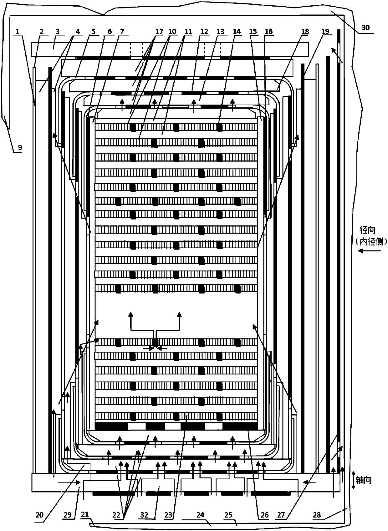
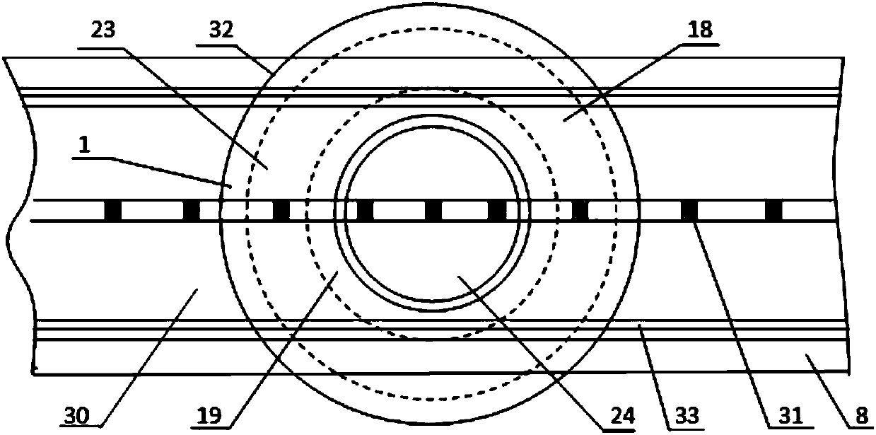
[0033] Such as Figure 1 to Figure 16 As shown, the present embodiment provides a body cooling structure for a transformer or a reactor, which includes a body body 32; the body body 32 includes a core 24, a coil 23 and a body insulation 29; the core 24 is composed of Core 28, iron yoke 21, iron yoke oil channel 31, clamp 8 and clamp insulation 33, iron yoke 21 is composed of lower yoke 25, upper yoke 30 and side yoke 9; coil 23 is composed of wire cake 10 and coil pad Block 11 constitutes; Body insulation 29 comprises the inner peripheral screen 19 between the inner diameter side of the coil 23 and the outer diameter side of the iron core post 28, the outer peripheral screen 1, the upper end insulation 18 and the lower end insulation 20 of the coil 23 outer diameter side; the inner peripheral screen 19 is formed by the coil Inner stay 15, coil inner paper tube 16, stay 4, paper tube 2, stem paper tube 27; peripheral screen 1 is composed of coil outer stay 7, coil outer paper t...


PUM


Abstract

The invention relates to a body cooling structure for a transformer or an electric reactor. The body cooling structure for the transformer or the electric reactor is characterized in that oil flow openings are formed in positions near the upper end and the lower end of a center column paper barrel, and the center column paper barrel is supported by an insulating cushion block of a lower iron yokecushion block; a plurality of iron yoke oil passages are arranged in an iron yoke; a plurality of axial oil passages are arranged in each wire cake of a coil, and the axial oil passages in the adjacent wire cakes are radially staggered from one another; a plurality of oil flow openings are formed in an upper-end insulator and a lower-end insulator; the iron yoke oil passages axially correspond tothe axial oil passages of the coil and the oil flow openings of the upper-end insulator and the lower-end insulator; oil flow openings are formed in the upper end and the lower end of a multilayer paper barrel. The body cooling structure for the transformer or the electric reactor has the advantages that the center column, body and coil cooling capacity can be improved; the body cooling structureis high in reliability, cooling capacity and low in cost and is simple, processes for the body cooling structure are simple, and a single column can be possibly used as single phase for the transformer or the electric reactor with extra-high capacity.

Description

technical field [0001] The invention relates to the field of transformers, in particular to a body cooling structure for transformers or reactors. Background technique [0002] When the capacity is large or very large, the loss of the coil and core column of the reactor or transformer is large, and the oil flow in the heat dissipation area is limited. The larger the temperature difference, the more prone to local overheating and reduced reliability. Therefore, in engineering practice, when the single-phase capacity of the reactor is 200,000 kVAr and above, and the single-phase capacity of the transformer is 334,000 kVAr and above, the manufacturers have to adopt the structure of using two or three columns as one phase. Two or three coils set on two or three core columns are used as coils of the same phase to separate the capacity. The capacity of each coil is 1 / 2 or 1 / 3 of the rated capacity. Of course, the loss and magnetic flux leakage are also separated. The electromagn...

Claims


Application Information

Patent Timeline
Patent Type & Authority Applications(China)
IPC IPC(8): H01F27/12H01F27/24H01F27/28H01F27/32
Inventor 禹云长禹东泽
Owner WUJIANG TRANSFORMER
Why Eureka
Try Eureka