A pump body of a rotary cylinder piston compressor and a compressor using the same

A compressor pump and piston technology, applied in the field of compressors, can solve problems such as insufficient oil volume of the rotary shaft pump, achieve the effects of solving abnormal wear problems, reducing oil output resistance, and increasing oil output

Active Publication Date: 2018-08-07
GREE ELECTRIC APPLIANCES INC +1
View PDF5 Cites 0 Cited by
  • Summary
  • Abstract
  • Description
  • Claims
  • Application Information

AI Technical Summary

Problems solved by technology

[0005] The purpose of the present invention is to provide a pump body of a rotary cylinder piston compressor, which can solve the problem of insufficient pump oil volume of the rotary shaft existing in the prior art

Method used


Image

  • A pump body of a rotary cylinder piston compressor and a compressor using the same
  • A pump body of a rotary cylinder piston compressor and a compressor using the same
  • A pump body of a rotary cylinder piston compressor and a compressor using the same

Examples


Embodiment approach 1

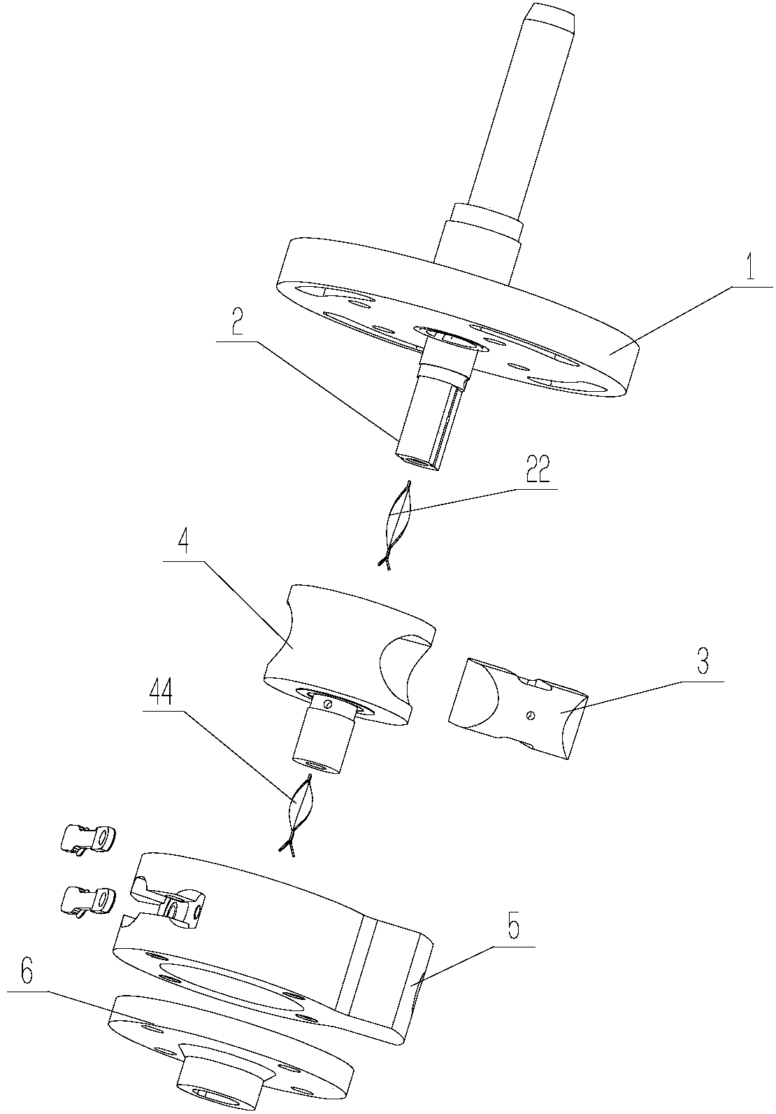
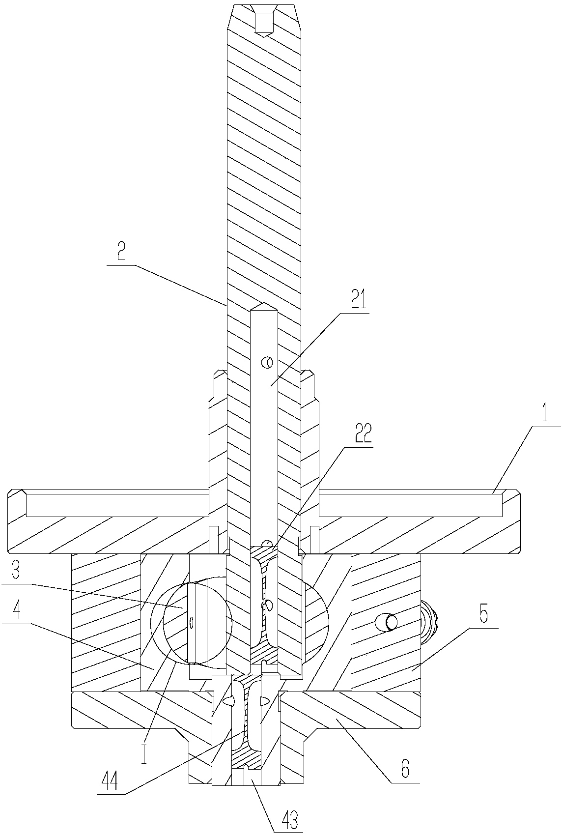
[0039] Such as Figure 1 to Figure 5 As shown, this embodiment provides a rotary cylinder piston compressor pump body, which includes an upper flange 1, a rotating shaft 2, a piston 3, a cylinder 4, a cylinder liner 5 and a lower flange 6, Wherein, the piston 3 is installed in the piston hole 41 of the cylinder 4, the cylinder short axis 42 of the cylinder 4 is installed on the lower flange 6, and the cylinder liner 5 is coaxially installed with the cylinder 4, and the lower flange 6 is fixed on the lower end of the cylinder liner 5, The piston supporting surface of the rotating shaft 2 is installed in cooperation with the piston plane, and the upper flange 1 fixes the upper half of the rotating shaft 2, and the upper flange 1 is fixed on the upper end of the cylinder liner 5 by screws.

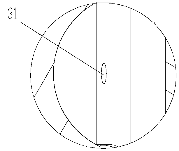
[0040] Specifically, the shaft 2 is provided with a shaft hole 21, and the cylinder 4 is provided with an oil guide channel communicating with the shaft hole 21, wherein the intersection area...

Embodiment approach 2

[0056] Such as Figure 6 to Figure 9 As shown, in this embodiment, another structural form of the oil guide channel is provided, refer to Figure 6 , Figure 7 , this oil guide passage is the oil guide pipe 7. Cylinder 4 comprises cylinder stub shaft 42, and this cylinder stub shaft 42 is provided with the through-hole structure 48 that is used for providing the movement space for the movement of oil guide pipe 7, and oil guide pipe 7 is arranged in the through-hole structure 48, and one end of oil guide pipe 7 is installed on On the rotating shaft 2 , the outlet end of the oil guiding pipe 7 is in contact with the rotating shaft hole 21 , and an oil guiding plate 8 is arranged in the oil guiding pipe 7 . The structure of the oil guide sheet is the same as that of the shaft hole oil guide sheet 22 mentioned in one embodiment.

[0057] In order to provide movement space for the oil guide pipe 7 , the inner diameter of the short shaft 42 of the cylinder is larger than that of...


PUM


Abstract

The invention relates to the technical field of compressors and particularly relates to a pump body of a rotary cylinder piston compressor and a compressor adopting the pump body. The pump body of the rotary cylinder piston compressor comprises a rotary shaft, a piston and an air cylinder, wherein the rotary shaft is internally provided with a rotary shaft hole; the air cylinder is internally provided with an oil-conducting channel communicated with the rotary shaft hole; and the crossed area of the rotary shaft hole and the oil-conducting channel is no smaller than 20% of the cross section area of the rotary shaft hole. Meanwhile, the invention further provides the compressor adopting the pump body of the rotary cylinder piston compressor. By enlarging the crossed area of the rotary shaft hole and the oil-conducting channel, the oil pumping amount of the rotary shaft can be increased; a sinking groove, an air cylinder oil hole and an air cylinder short shaft hole are arranged so that the oil discharging resistance of an oil hole in the side face of the rotary shaft is reduced and the oil outlet quantity of the oil hole of the rotary shaft is increased; and the problem of abnormal abrasion caused by the fact that the lubrication between the side face of the rotary shaft and the piston is not enough under a heavy working condition is effectively solved.

Description

technical field [0001] The invention relates to the technical field of compressors, in particular to a pump body of a rotary cylinder piston compressor and a compressor using the same. Background technique [0002] The rotary cylinder piston compressor belongs to a new structure of refrigeration piston compressors, which essentially adopts a cross slider structure principle. refer to Figure 10 , O1 is the center of the rotating shaft, O2 is the center of the cylinder, e is the distance between the centers of circles (that is, the eccentricity of the compressor), and the square is the center of mass of the piston. When the rotating shaft rotates, it drives the piston to perform circular motion, and the distance between the piston and the center of the cylinder runs within the range of 0-e. The rotating shaft is assembled eccentrically with the cylinder, and the rotating shaft drives the cylinder to rotate through the piston. Due to the eccentric relationship between the ro...

Claims


Application Information

Patent Timeline
Patent Type & Authority Patents(China)
IPC IPC(8): F04C29/02F04C18/34
CPCF04C18/34F04C29/02F04C29/023F04C2240/603
Inventor 黄辉胡余生邓丽颖杜忠诚徐嘉
Owner GREE ELECTRIC APPLIANCES INC
Why Eureka
Try Eureka