Spiral oil suction pipe for refrigerator compressor

A technology for refrigerator compressors and oil suction pipes, which is applied to mechanical equipment, machines/engines, liquid variable capacity machines, etc. It can solve the problems of affecting the service life of frequency conversion compressors, damage of frequency conversion compressors, and large oil pump resistance, etc., to achieve Long service life, small oil absorption resistance and large pump oil volume

Inactive Publication Date: 2015-03-25
HUAYI COMPRESSOR (JINGZHOU) CO LTD
View PDF5 Cites 0 Cited by
  • Summary
  • Abstract
  • Description
  • Claims
  • Application Information

AI Technical Summary

Problems solved by technology

[0003] The object of the present invention is to provide an internal helical tube structure, which is fixed through the center hole of the motor rotor and connected to the end face of the crankshaft. It is formed by injection molding at one time. The structure and manufacturing process are simple, easy to assemble, small oil absorption resistance, and large pump oil volume , the lubricating effect is good, and the reliability of the compressor is improved; to solve the problem that the existing oil suction pipe adopts the external thread structure, which makes the pump oil resistance large and the pump oil volume small, which is easy to cause lubrication failure, resulting in damage to the frequency conversion compressor, which seriously affects the frequency conversion compression Spiral oil suction pipe for refrigerator compressor due to machine life problem

Method used


Image

  • Spiral oil suction pipe for refrigerator compressor
  • Spiral oil suction pipe for refrigerator compressor
  • Spiral oil suction pipe for refrigerator compressor

Examples


Embodiment Construction

[0015] Embodiments of the present invention are described in detail below in conjunction with accompanying drawings:

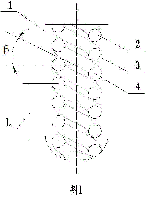
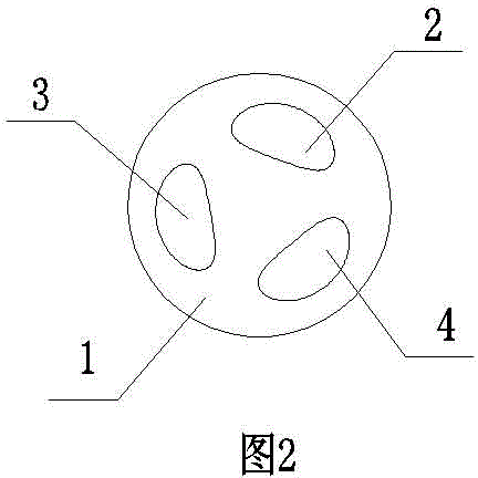
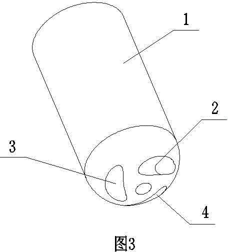
[0016] The spiral oil suction pipe used for refrigerator compressors is composed of an oil suction pipe body 1 and an embedded spiral pipe. The oil suction pipe body 1 is in the shape of a cylinder, and more than one columnar embedded spiral pipe is formed in the oil suction pipe body 1. The embedded spiral pipe is coaxial with the oil suction pipe main body 1, and the oil suction pipe main body 1 is connected with the end surface of the crankshaft 5 after being fixed through the central hole of the motor rotor 6.

[0017] The embedded spiral pipeline can be composed of an embedded spiral pipeline a2; it can also be composed of two spiral pipelines, the embedded spiral pipeline a2 and the embedded spiral pipeline b3; it can also be formed by the embedded spiral pipeline a2 1, embedded spiral pipeline b3 and embedded spiral pipeline c4 are composed of three spi...


PUM


Abstract

The invention relates to a spiral oil suction pipe for a refrigerator compressor, and belongs to the technical field of refrigeration compressor accessories. The spiral oil suction pipe comprises an oil suction pipe main body and embedded internal spiral grooves, wherein the cylindrical embedded internal spiral grooves are formed in the oil suction pipe main body, coaxial with the oil suction pipe main body, and distributed in the oil suction pipe main body at equal intervals in the axial direction; all of the lead angles beta are 27 degrees, and all of the threaded intervals L are 11 mm; one end of the oil suction pipe main body is fixedly connected with a crankshaft. The spiral oil suction pipe disclosed by the invention uses an embedded spiral pipeline structure, and is low in oil suction resistance, high in pumping oil capacity, good in lubricating effect, and long in service life as the embedded spiral pipeline structure is fixed through a center hole of a motor rotor and connected with the end face of a crankshaft; the compressor is stable and reliable in working; the spiral oil suction pipe can be injected and molded in a one-step manner, so that the spiral oil suction pipe is simple in manufacturing technology and convenient to assemble; the spiral oil suction pipe solves the problems that the existing oil suction pipe is high in oil pumping resistance and low in oil pumping capacity, and has high probability of causing lubrication failure to influence the service life of the variable-frequency compressor as an external thread structure is used, and the oil suction pipe is assembled together with the crankshaft through a tail sleeve.

Description

technical field [0001] The invention relates to a spiral oil suction pipe for a refrigerator compressor, belonging to the technical field of refrigeration compressor accessories. Background technique [0002] The oil suction pipe is a key part of the variable frequency compressor. After the oil suction pipe is assembled with the tail sleeve, the tail sleeve is assembled with the crankshaft or the motor rotor to form a tight fit structure. The lubricating oil of the compressor must pass through the oil suction pipe to enter the spiral groove on the outside of the crankshaft to lubricate the crankshaft and the shaft hole of the machine base. The head plays an important role in cooling, reducing component wear, reducing noise, and reducing friction loss. Therefore, the quality of the oil suction pipe and the tightness of the connection directly affect the service life of the entire inverter compressor. Due to the large variation range of the crankshaft speed of the frequency c...

Claims


Application Information

Patent Timeline
Patent Type & Authority Applications(China)
IPC IPC(8): F04B39/02
Inventor 冯皓陈远斌范洪兴张昌祥王立津
Owner HUAYI COMPRESSOR (JINGZHOU) CO LTD
Why Eureka
Try Eureka