Lubrication structure of a high-speed planetary reducer

A planetary reducer and lubricating structure technology, applied in the mechanical field, can solve the problems of high noise, unbalanced locking sleeve, small range of motor shaft diameter, etc., and achieve the effect of low noise and stable connection rotation

Active Publication Date: 2018-09-21
WANSHSIN SEIKOU HUNAN CO LTD
View PDF6 Cites 0 Cited by
  • Summary
  • Abstract
  • Description
  • Claims
  • Application Information

AI Technical Summary

Problems solved by technology

However, since the above-mentioned structure is not completely symmetrical, and for different motor shafts, the degree of tightening the threaded holes of the bolts is different, which causes the lock sleeve to be unbalanced, which makes the reducer prone to vibration and other phenomena when it is running at high speed, and The noise is high. In addition, the range of the motor shaft diameter adapted to this structure is small.

Method used


Image

  • Lubrication structure of a high-speed planetary reducer
  • Lubrication structure of a high-speed planetary reducer
  • Lubrication structure of a high-speed planetary reducer

Examples


Embodiment 1

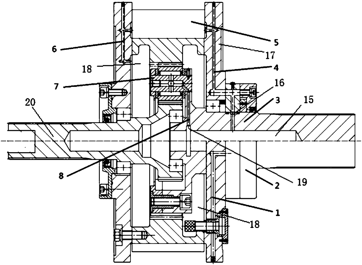
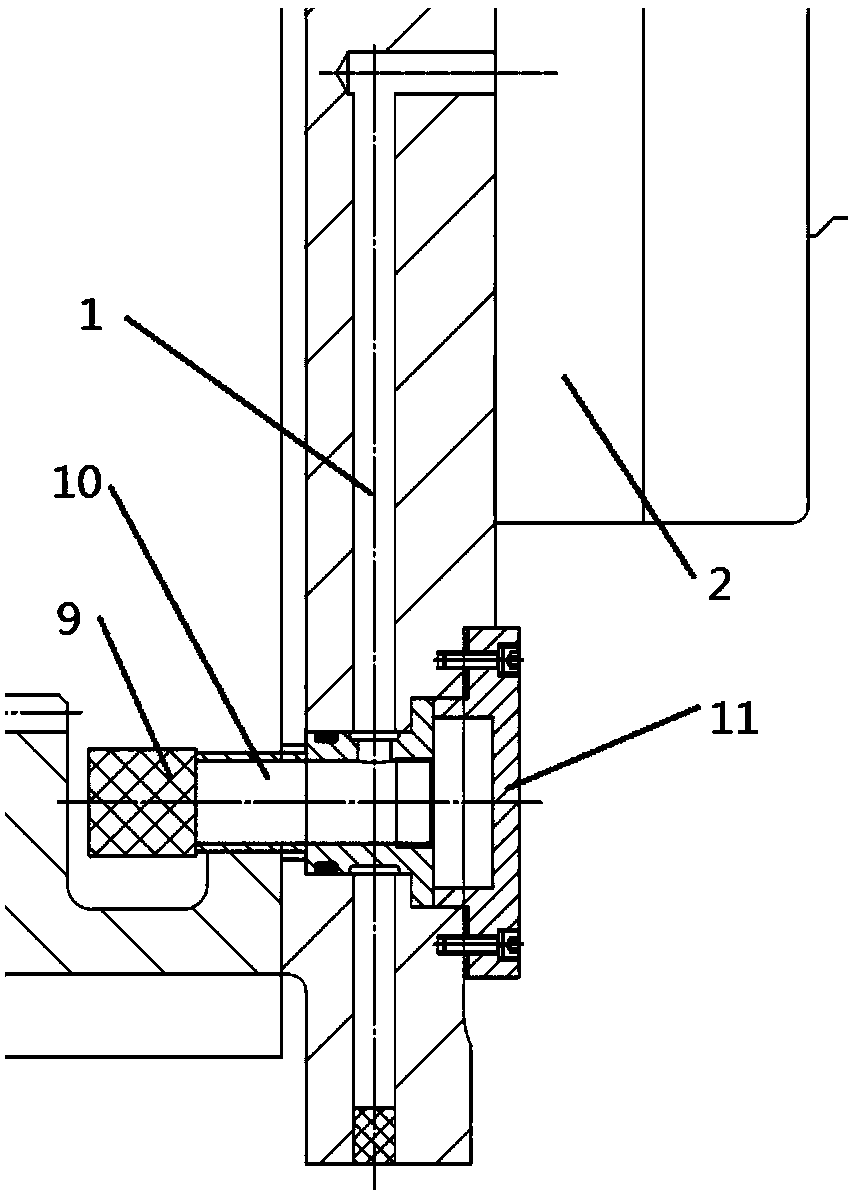
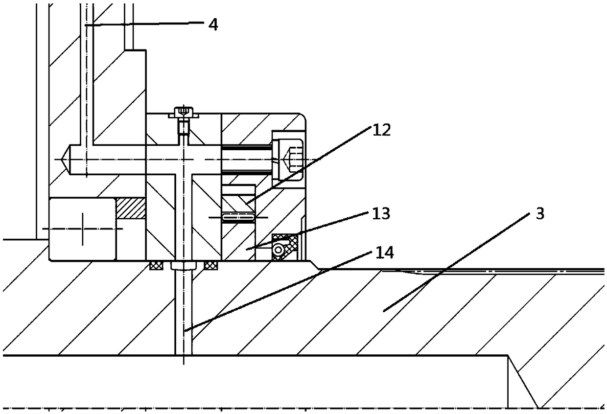
[0028] Such as Figure 1-3 The lubrication structure of a high-speed planetary reducer shown includes a housing 17, a gear mechanism 7 is installed in the housing 17, a box 18 is formed between the gear mechanism 7 and the housing 17, and the gear mechanism 7 is connected to the output shaft 3. The output shaft 3 is formed with a cavity 15 for containing lubricating oil, and the output shaft 3 is formed with an outer oil groove 16. The cavity 15 communicates with the outer oil groove 16 through the output shaft pressure oil passage 14, and the outer casing 17 is formed with an outer oil groove 16. Connected pressure oil passage 4, a radiator 5 is installed above the casing 17, and the pressure oil passage 4 surrounds the radiator 5 to dissipate heat and spray lubricating oil on the gear mechanism 7; the lower part of the box body 18 communicates with the gear oil pump through the negative pressure oil passage 1 2. The gear oil pump 2 is connected with the outer oil tank 16; th...

Embodiment 2

[0035] Such as Figure 5-7 As shown, the gear mechanism 7 is connected with an input shaft 20, and the input shaft 20 is locked and connected with the motor shaft 22 through a locking sleeve 21. The locking sleeve 21 includes a locking sleeve body 23, and the locking sleeve body 23 is symmetrically provided with The vertical groove 24 and the locking sleeve body 23 on both sides of the vertical groove 24 are connected through the upper ring body 25 , and are formed with opposite threaded holes 27 , and the upper ring body 25 is provided with a horizontal groove 26 perpendicular to the vertical groove 24 .

[0036] The vertical groove 24 is on the central axis of the horizontal groove 26 .

Embodiment 3

[0038] In order to ensure the wear resistance of the sun gear and the planetary gear in the gear mechanism, the composition of the sun gear and the planetary gear is as follows: zinc 83-86%, iron 4-8%, aluminum 2-8%, silicon 2.4-3%, carbon 0.1% ~1%, copper 0.2~0.5%, magnesium 0.5~1%, vanadium 0.1~0.5%, chromium 0.005~0.007%, lead 0.002~0.005%, titanium 0.003~0.008%. Add the above materials into the furnace in proportion, heat at high temperature to melt, stir, and the heating rate is 6 degrees Celsius per minute and 3 degrees Celsius per minute, mixed and heated alternately; the melting time is 2.5 to 3 hours, stirring once every half an hour, Stir for 1 to 3 minutes each time; then transport the molten metal to the holding furnace, then inject it into the die-casting machine for die-casting, cool down, and obtain the preliminary products of the sun gear and the planetary gear, and then polish and drape to obtain the final product. After testing, the elongation performance, te...


PUM


Abstract

The invention discloses a lubricating structure of a high-speed planetary reducer. The lubricating structure comprises a housing, wherein a gear mechanism is mounted in the housing; a box body is formed between the gear mechanism and the housing; the gear mechanism is connected with an output shaft; a cavity for containing lubricating oil is formed in the output shaft; an outer oil slot is formedoutside the output shaft; the cavity communicates with the outer oil slot through an output shaft pressure oil path; a pressure oil path which communicates with the outer oil slot is formed in the housing; a radiator is mounted above the housing; after radiating around the radiator, the pressure oil path sprays lubricating oil onto the gear mechanism; the lower part of the box body communicates with a gear oil pump through a negative-pressure oil path; the gear oil pump communicates with the outer oil slot; and the gear oil pump is connected with the output shaft. The lubricating structure does not need to provide power of an oil pump in an additional mode, can regulate an oil pumping rate in real time according to operation speed of the planetary reducer, applies lubricating oil to radiate to help the reducer to quicken radiating; and moreover, a special fixed sleeve structure is adopted, so that operation of the reducer is more stable.

Description

technical field [0001] The invention belongs to the field of machinery, and in particular relates to a lubricating structure of a high-speed planetary reducer. Background technique [0002] When the planetary gear of the reducer is running at high speed, it needs lubricating oil for lubrication, but the existing high-speed and heavy-duty planetary gear reducer has low lubrication efficiency, and the amount of lubricating oil cannot be adjusted according to the needs, so it needs to be improved. In addition, the reducer runs at high speed When a large amount of heat is generated, a heat dissipation structure is also required for heat dissipation. Finally, the input shaft of the reducer generally connects the output shaft with the driven mechanism through a locking sleeve, but the existing locking sleeve is radially on a plane in order to keep it fixed, so it is an integral structure, such as Figure 4 As shown, a groove is set on one side, and the upper threaded hole and the ...

Claims


Application Information

Patent Timeline
Patent Type & Authority Patents(China)
IPC IPC(8): F16H57/04
Inventor 周清泉
Owner WANSHSIN SEIKOU HUNAN CO LTD
Why Eureka
Try Eureka