
Dedicated automatic separating-placing machine for traffic cones for road traffic construction site facility protection

A construction site, automatic separation technology, applied in the direction of roads, roads, road signs, etc., can solve the problems of high labor intensity, inconvenient handling of stacked road cones, and easy danger

Inactive Publication Date: 2017-10-13
安徽海之纳科技有限公司
View PDF0 Cites 6 Cited by
  • Summary
  • Abstract
  • Description
  • Claims
  • Application Information

AI Technical Summary

Problems solved by technology

[0003] In order to solve the above problems, the present invention provides a special road cone automatic separation and placement machine for the protection of road traffic construction site facilities, which can solve the problems of low work efficiency, high labor intensity, and easy danger caused by manual operation when the existing road cones are separated and placed. , The whole stack of road cones is inconvenient to take and it is easy to fall when placing the road cones. It realizes the function of automatic separation and stable placement of the whole stack of road cones. The advantage of being dangerous, the stacked road cones are automatically separated and the road cones will not fall when placed

Method used


Image

  • Dedicated automatic separating-placing machine for traffic cones for road traffic construction site facility protection
  • Dedicated automatic separating-placing machine for traffic cones for road traffic construction site facility protection
  • Dedicated automatic separating-placing machine for traffic cones for road traffic construction site facility protection

Examples


Embodiment Construction

[0027] In order to make the technical means, creative features, objectives and effects achieved by the present invention easy to understand, the present invention will be further described below in conjunction with specific illustrations. It should be noted that, in the case of no conflict, the embodiments in the present application and the features in the embodiments can be combined with each other.

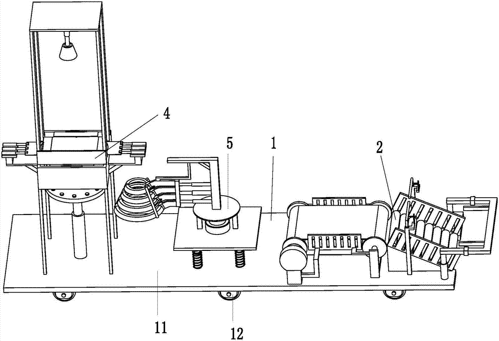
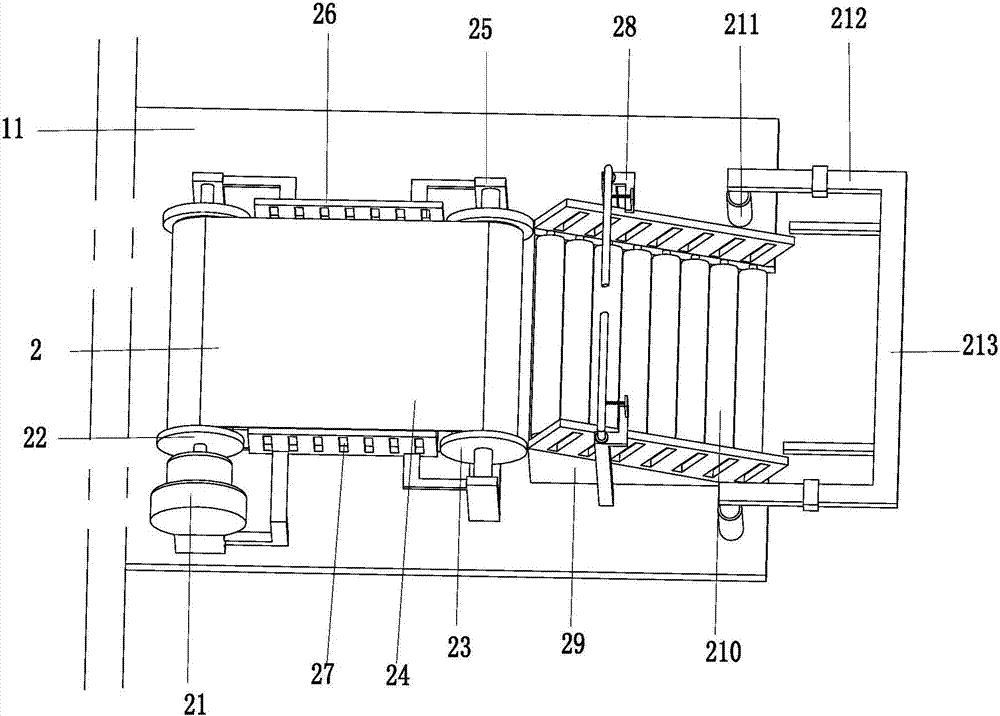
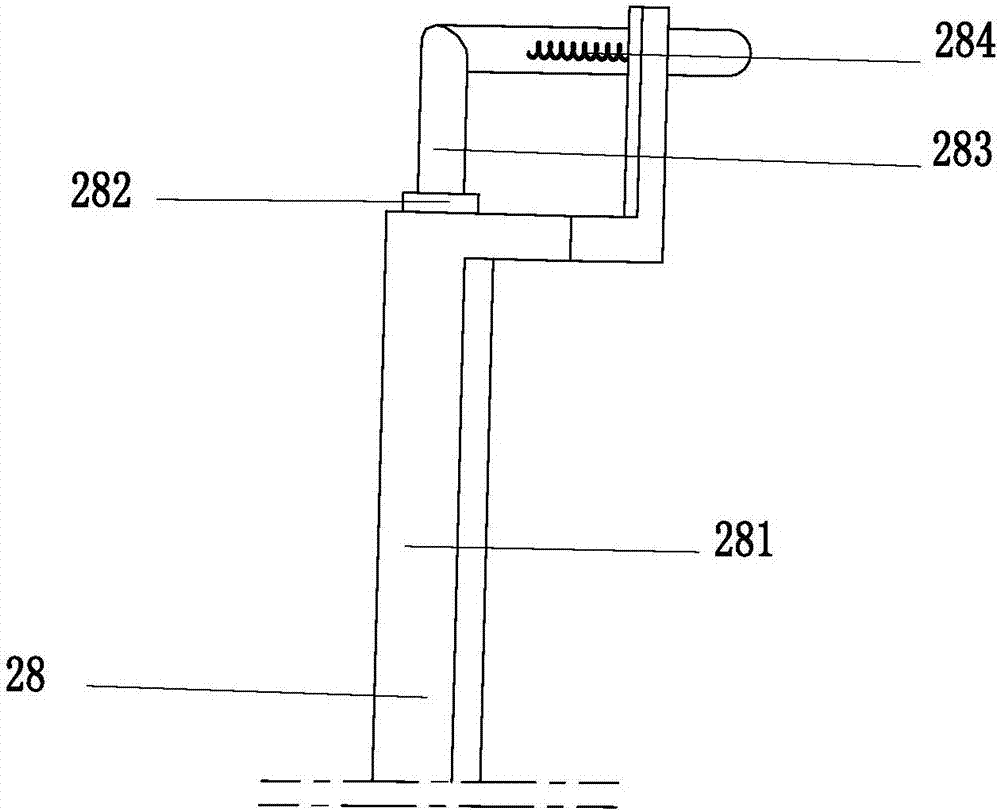
[0028] Such as Figure 1 to Figure 7 As shown, a road cone automatic separation and placement machine for protecting road traffic construction site facilities includes a base 1, an automatic placement device 2, a separation device 4 and a grabbing and placing device 5. The base 1 includes a bottom plate 11 and six Two universal wheels 12, six universal wheels 12 are symmetrically installed on the bottom of the base plate 11; And the pick and place device 5 is installed on the bottom plate 11 , the separation device 4 is installed on the bottom plate 11 , and the separation devi...


PUM


Abstract

The invention relates to an automatic separation and placement machine for road cones dedicated to protecting road traffic construction site facilities, which includes a base, an automatic placement device, a separation device and a grabbing and placing device. Two universal wheels are symmetrically installed on the bottom of the base plate; the automatic placing device is installed on the right side of the base plate, the grabbing and placing device is located on the left side of the automatic placing device, and the grabbing and placing device is installed on the base plate, and the separation device is installed On the base plate, the separation unit is located to the left of the pick and place unit. The present invention can solve the problems of low work efficiency, high labor intensity, danger caused by manual operation, inconvenient taking of stacked road cones and uneven placement of existing road cones, and realizes the whole stacking of road cones. The functions of automatic transportation, separation and placement have the advantages of high operating efficiency, fully mechanized operation, no danger caused by mechanized operation, automatic separation of stacked road cones and uniform placement.

Description

technical field [0001] The invention relates to the field of road cone placement equipment, in particular to a special road cone automatic separation and placement machine for protecting road traffic construction site facilities. Background technique [0002] Road cones, also known as roadblocks, are used to place in the middle of the road, dangerous areas and road construction sites, etc., and are located around places that need to temporarily separate traffic flow, guide traffic, guide vehicles to bypass dangerous road sections, protect construction site facilities and personnel, or other appropriate Place. It is generally used in urban intersection lanes, highway maintenance, traffic police law enforcement, road administration law enforcement, hotels, residential areas, sports venues, dangerous areas, road construction and other areas; the placement of road cones is generally done manually, and there is a need for placing road cones in this working method. It is necessar...

Claims


Application Information

Patent Timeline
IPC IPC(8): B65G59/10B65G61/00B65G47/82B65G47/52E01F9/70
CPCB65G59/10B65G47/52B65G47/82B65G61/00E01F9/70
Inventor 沈永根
Owner 安徽海之纳科技有限公司
Learn More