
COA substrate formed directly by splicing photomasks and display panel

A direct and mask technology, applied in optics, nonlinear optics, instruments, etc., can solve problems such as poor display, left or right deviation, different colors, etc., and achieve the effect of improving poor display

Active Publication Date: 2017-10-13
TCL CHINA STAR OPTOELECTRONICS TECH CO LTD
View PDF7 Cites 3 Cited by
  • Summary
  • Abstract
  • Description
  • Claims
  • Application Information

AI Technical Summary

Problems solved by technology

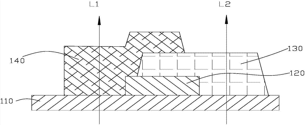
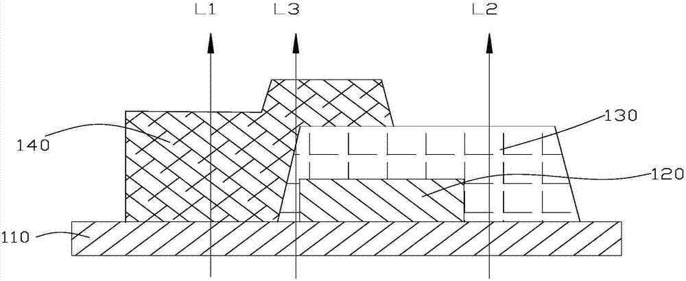
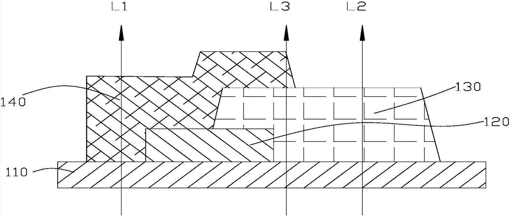
In the process of forming the first color-resist layer 130 and the second color-resist layer 140, the first color-resist layer 130 and the second color-resist layer 140 are respectively formed by the direct splicing technology of the photomask, and the photomask may go to Shifting to the left or shifting to the right causes the overlapping area of ​​the first color-resist layer 130 and the second color-resisting layer 140 to move to the left or to the right relative to other overlapping areas of the COA substrate at the joint of the photomask, resulting in the first The overlapping area of ​​the first color-resist layer 130 and the second color-resist layer 140 partially exceeds the range of the first metal line 120 (see FIG. Figure 1b and Figure 1c ), at this time, the light transmitted from the backlight is divided into three types (the light below the first metal line 120 is blocked by the first metal line 120 and cannot be transmitted): the first light is only transmitted through the first color resist layer 130, the second type of light is transmitted only through the second color-resist layer 140, the third type of light is transmitted through the overlapping area of ​​the first color-resist layer 130 and the second color-resist layer 140 beyond the range of the first metal line 120, the third type of light The colors of the first color-resist layer 130 and the second color-resist layer 140 are combined, which is not what the designer wants the user to see, causing the user to see the third light, resulting in the color and display of the direct splicing of the corresponding photomask on the display panel Other areas of the panel are colored differently, resulting in mura

Method used


Image

  • COA substrate formed directly by splicing photomasks and display panel
  • COA substrate formed directly by splicing photomasks and display panel
  • COA substrate formed directly by splicing photomasks and display panel

Examples


Embodiment Construction

[0030] The following will clearly and completely describe the technical solutions in the embodiments of the present invention with reference to the accompanying drawings in the embodiments of the present invention. Obviously, the described embodiments are only some, not all, embodiments of the present invention. Based on the embodiments of the present invention, all other embodiments obtained by persons of ordinary skill in the art without creative efforts fall within the protection scope of the present invention.

[0031] The terms "comprising" and "having" and any variations thereof appearing in the specification, claims and drawings of this application are intended to cover non-exclusive inclusion. For example, a process, method, system, product or device comprising a series of steps or units is not limited to the listed steps or units, but optionally also includes unlisted steps or units, or optionally further includes For other steps or units inherent in these processes, ...


PUM

PropertyMeasurementUnit
Widthaaaaaaaaaa

Abstract

An embodiment of the invention discloses a COA substrate formed directly by splicing photomasks. The COA substrate comprises an array substrate, metal lines formed on the array substrate, a first color resistance layer formed on the array substrate and partly positioned on the metal line and a second color resistance layer formed on the array substrate and partly positioned on the metal line, the first color resistance layer and the second color resistance layer are overlapped partly at least, the metal lines include first metal lines, the first metal lines correspond to positions where the photomasks are directly spliced, and width of the first metal lines is greater than width of a first overlapped area of the first color resistance layer and the second color resistance layer corresponding to the first metal lines by 2-6 mu m to enable the first overlapped area to be positioned in a range of the first metal lines. The embodiment of the invention further discloses a display panel. The COA substrate has the advantage that bad display effect caused by photomask shift in the process of directly splicing the photomasks can be improved.

Description

technical field [0001] The invention relates to the field of display technology, in particular to a COA substrate and a display panel formed by direct splicing of photomasks. Background technique [0002] At present, when making large-size display panels, because the size of the product exceeds the typesetting size of the mask (mask), splicing exposure is required to convert the mask pattern to the large-size display panel. The splicing technology currently used includes direct mask splicing technology, mask The direct splicing technology is specifically: first place the mask on one side of the substrate for the first exposure, and then move the mask to the unexposed area adjacent to the first exposure area for the second exposure, if the display panel The size is large, and multiple exposures can be performed. This direct splicing technology of the mask solves the exposure problem of large-size display panels. [0003] Existing display panels include COA (Color Filter On A...

Claims


Application Information

Patent Timeline
IPC IPC(8): G02F1/1362
CPCG02F1/136286G02F1/136222
Inventor 袁继旺
Owner TCL CHINA STAR OPTOELECTRONICS TECH CO LTD
Learn More