
LED glue dispensing packaging device

A technology of glue sealing and installing cabinets, which is applied to the device and coating of the surface coating liquid, which can solve the problems of reducing the speed of dispensing and packaging of LED boards, overflowing of dispensing head packaging glue, and affecting the appearance of LED boards, etc., to achieve Easy to remove and fix, fast dispensing speed, and easy to use

Active Publication Date: 2017-10-17
绍兴市上虞区思亿电器有限公司
View PDF7 Cites 4 Cited by
  • Summary
  • Abstract
  • Description
  • Claims
  • Application Information

AI Technical Summary

Problems solved by technology

[0002] At present, LED packaging usually adopts the method of dispensing glue. When dispensing glue, first fix the LED board, and then manually control the movement of the dispensing head, so as to realize the relative movement between the dispensing head and the LED board, so as to fix the fixed LED board. However, manually controlling the movement of the dispensing head to dispensing glue on the LED board will cause uneven dispensing, and it will also cause overflow and sticking of the packaging glue in the dispensing head, which will affect the appearance of the LED board. , and requires a lot of labor, wasting human resources, greatly reducing the speed of dispensing and packaging of LED boards, and reducing production efficiency. Although there are some fully automatic dispensing and packaging equipment, these equipment are expensive to use and complicated to operate. promotional use

Method used


Image

  • LED glue dispensing packaging device
  • LED glue dispensing packaging device
  • LED glue dispensing packaging device

Examples


Embodiment Construction

[0018] The preferred embodiments of the present invention will be described in detail below in conjunction with the accompanying drawings, so that the advantages and features of the present invention can be more easily understood by those skilled in the art, so as to define the protection scope of the present invention more clearly.

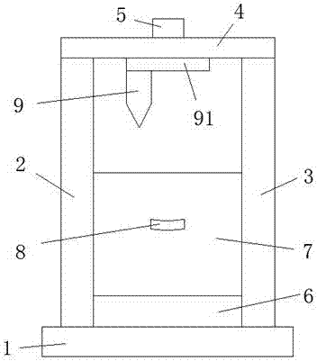
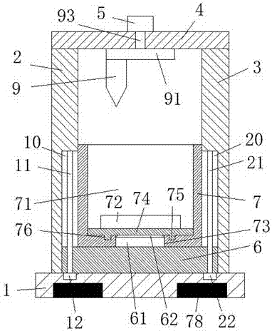
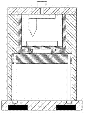
[0019] refer to Figure 1-5 The shown LED dispensing packaging device includes a base 1, a counterweight 78 arranged at the bottom of the base 1, and a left column 2 and a right column 3 relatively arranged at the left and right ends of the top of the base 1, and The horizontal plate 4 arranged on the top of the left column 2 and the right column 3, the top of the horizontal plate 4 is provided with a first motor 5, and the bottom of the horizontal plate 4 is rotatable between the left column 2 and the right column 3 Rotary disc 91 is provided, and the dispensing head 9 is arranged at the bottom of the rotary disc 91, and the rotary disc 91 is co...


PUM


Abstract

The invention discloses an LED glue dispensing packaging device. The LED glue dispensing packaging device comprises a base, a weight-balance mass block, a left vertical column, a right vertical column and a transversal plate, wherein the weight-balance mass block is arranged at the bottom of the base, the left vertical column and the right vertical column are oppositely arranged at the left side and the right side of the top of the base, and the transversal plate is arranged at the top of the left vertical column and the right vertical column; a first electromotor is arranged at the top of the transversal plate, and a revolving disc is revolvably arranged at the bottom, between the left vertical column and the right vertical column, of the transversal plate; and a glue dispensing head is arranged at the bottom of the revolving disc, the revolving disc is connected with the first electromotor through the rotating shaft, and the rotating shaft penetrates through the transversal plate and is revolvably connected with the transversal plate in a matched mode. The overall LED glue dispensing packaging device is simple in structure, low in manufacturing cost, easy to operate, convenient to use, and glue dispensing packaging efficiency of an LED plate is significantly improved, glue dispensing operation controlled manually can be replaced, labor cost is saved, glue dispensing speed is fast, precision is high, and the LED glue dispensing packaging device is suitable for popularizing and using.

Description

technical field [0001] The invention relates to the technical field of LED packaging, in particular to an LED dispensing packaging device. Background technique [0002] At present, LED packaging usually adopts the method of dispensing glue. When dispensing glue, first fix the LED board, and then manually control the movement of the dispensing head, so as to realize the relative movement between the dispensing head and the LED board, so as to fix the fixed LED board. However, manually controlling the movement of the dispensing head to dispensing glue on the LED board will cause uneven dispensing, and it will also cause overflow and sticking of the packaging glue in the dispensing head, which will affect the appearance of the LED board. , and requires a lot of labor, wasting human resources, greatly reducing the speed of dispensing and packaging of LED boards, and reducing production efficiency. Although there are some fully automatic dispensing and packaging equipment, these ...

Claims


Application Information

Patent Timeline
Patent Type & Authority Applications(China)
IPC IPC(8): B05C5/02B05C13/02
CPCB05C5/0208B05C13/02
Inventor 林凤英
Owner 绍兴市上虞区思亿电器有限公司
Learn More