
Ejector device with movable working nozzle

An ejector and nozzle technology, applied in the field of ejectors, can solve the problems of restricting the use of ejectors and failing to reach the ejection ratio, etc., so as to improve the ejection performance, increase the ejection ratio, and increase the ejection amount Effect

Active Publication Date: 2017-10-17
XI AN JIAOTONG UNIV
View PDF5 Cites 10 Cited by
  • Summary
  • Abstract
  • Description
  • Claims
  • Application Information

AI Technical Summary

Problems solved by technology

[0004] Due to the fixed structure and other parameters of the existing ejectors, the best ejection capability can only be achieved under specific working conditions
However, when the working conditions change, the best injection ratio cannot be reached, which limits the use of the ejector

Method used


Image

  • Ejector device with movable working nozzle
  • Ejector device with movable working nozzle
  • Ejector device with movable working nozzle

Examples


Embodiment Construction

[0026] The present invention will be further described in detail below in conjunction with specific embodiments, which are explanations of the present invention rather than limitations.

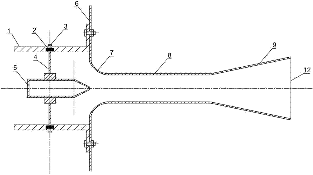
[0027] see figure 1 , the ejector device with movable working nozzle disclosed in the present invention includes a working nozzle 5 and an ejector main body 12, and the ejector main body 12 is composed of a shrinkage tube 7, a mixing tube 8 and a diffuser tube 9, and is characterized in that, The working nozzle 5 is connected to the welded disk 6 of the shrink tube 7 through a connecting piece, so that the working nozzle 5 can move horizontally along the central axis of the injector body 12 .

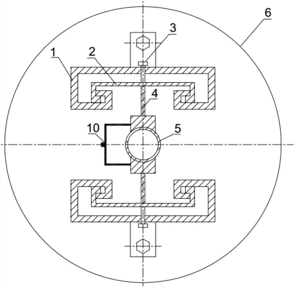
[0028] to combine figure 1 and figure 2 , the connecting piece includes a slideway 1 and a slider 2 capable of sliding in the slideway 1, the slideway 1 is fixedly connected with the disc 6 welded to the shrink tube 7, preferably, the slideway 1 is fixed on the guide with bolts On the injector body...


PUM


Abstract

The invention discloses an ejector device with a movable working nozzle, and belongs to the field of ejectors. The working nozzle is connected with a shrinking pipe of an ejector main body through a connecting piece, so that the working nozzle can move in the central axis direction of the ejector main body. The distance between the exit port of the nozzle and the throat part of the ejector can be changed to reach an optimal value, so that ejection capacity of the ejector for lower pressure gas is improved, the ejection ratio is increased, working performance of the ejector is improved. The ejector device with the movable working nozzle is not affected by kinds of the ejector, the design of the ejector device with the movable working nozzle can be used for all different ejectors, the distance between the exit port of the working nozzle and the throat part of the ejector is adjusted, the ejection ratio is increased, and the ejection performance of the ejector is improved.

Description

technical field [0001] The invention belongs to the field of ejectors, and relates to an ejector device for mixing high-pressure fluid and low-pressure fluid, in particular to an ejector device with a movable working nozzle. Background technique [0002] The ejector can use high-pressure fluid to eject low-pressure fluid without directly consuming mechanical work, thereby increasing the pressure of low-pressure fluid. It has a simple structure, no moving parts, and is convenient for manufacture and maintenance. Ejectors are widely used in various fields, such as industrial thermal processing, refrigerators, burners, aviation ships, etc. [0003] The ejection performance of the ejector is generally characterized by the ejection ratio, which refers to the ratio of the flow rate of the ejected fluid to the flow rate of the ejected fluid. The ejection ratio is related to many factors, such as the pressure of the ejected fluid, the outlet back pressure of the ejector, the struct...

Claims


Application Information

Patent Timeline
Patent Type & Authority Applications(China)
IPC IPC(8): F04F5/46
CPCF04F5/461
Inventor 王跃社尚阳陈涛
Owner XI AN JIAOTONG UNIV
Learn More