A flying probe test device

A flying probe test and stylus technology, which is used in printed circuit testing, electronic circuit testing and other directions, can solve the problems of low mechanical precision and complex structure of modules, solve three-dimensional layout problems, meet performance requirements, and improve installation and positioning accuracy. Effect

Active Publication Date: 2020-02-18
BEIJING SEMICON EQUIP INST THE 45TH RES INST OF CETC
View PDF10 Cites 2 Cited by
  • Summary
  • Abstract
  • Description
  • Claims
  • Application Information

AI Technical Summary

Problems solved by technology

[0004] Multi-flying probe test equipment is widely used due to its high efficiency and fast test speed. However, due to the complex structure, the module structure method is often used. However, due to the low mechanical precision of the module, high-precision substrate testing cannot be performed.

Method used


Image

  • A flying probe test device
  • A flying probe test device

Examples


Embodiment Construction

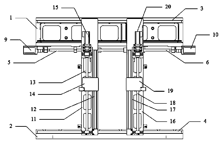
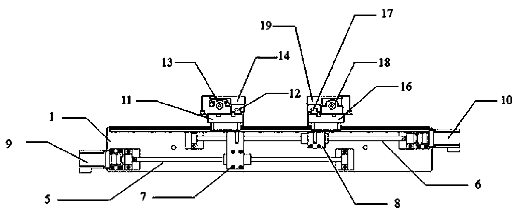
[0031] A flying probe testing device according to the present invention will be described in detail below in conjunction with specific embodiments and accompanying drawings.

[0032] The examples described here are specific specific implementations of the present invention, and are used to illustrate the concept of the present invention. They are all explanatory and exemplary, and should not be construed as limiting the implementation of the present invention and the scope of the present invention. In addition to the embodiments described here, those skilled in the art can also adopt other obvious technical solutions based on the claims of the application and the contents disclosed in the description, and these technical solutions include adopting any obvious changes made to the embodiments described here. Replacement and modified technical solutions.

[0033] The accompanying drawings in this specification are schematic diagrams, which assist in explaining the concept of the ...


PUM


Abstract

The invention discloses a flying probe test device. The device comprises a supporting base, X-direction units, a Y-direction unit and a measuring probe load unit. The X-direction units and the Y-direction unit are arranged on the supporting base. The measuring probe load unit is arranged on the Y-direction unit. The supporting base comprises a rear supporting base and a front supporting base, wherein the two supporting bases are fixed on a flying probe test platform in the parallel manner. A rear track pair is arranged on the rear supporting base, and a front track pair is arranged on the front supporting base. A plurality of X-direction units are arranged on the supporting base. The supporting plate of the Y-direction unit is arranged on the track pairs of the supporting base. The flying probe test device is reasonable in structure, and the positioning accuracy of a flying probe is effectively improved. The three-dimensional layout problem of multiple flying probe test structures in the space range can be solved. Therefore, the performance requirements of the flying probe high-speed movement can be met.

Description

technical field [0001] The invention relates to the technical field of printed circuit board detection, in particular to a flying probe testing device. Background technique [0002] In recent years, with the rapid development of the semiconductor industry, the use of electronic products has become more and more extensive, and the number of uses has also increased, so printed circuit boards have become more and more important. Therefore, the requirements for printed circuit board monitoring equipment are increasing higher. [0003] Flying probe testing is the latest solution to some of the major problems in electrical testing today. It replaces the bed of needles with a probe, using multiple motor-driven, fast-moving electrical probes to make contact with the pins of the device and make electrical measurements. [0004] Multi-flying probe test equipment is widely used due to its high efficiency and fast test speed. However, due to the complex structure, the module structure...

Claims


Application Information

Patent Timeline
Patent Type & Authority Patents(China)
IPC IPC(8): G01R31/28
CPCG01R31/2808
Inventor 李燕玲吕磊高慧莹左宁
Owner BEIJING SEMICON EQUIP INST THE 45TH RES INST OF CETC
Why Eureka
Try Eureka