A rotary trigger device and vertical intelligent steel coil fixture

A technology for triggering devices and clamps, which is applied in the directions of safety devices, transportation and packaging, and load hanging components, etc. It can solve the problems of large impact force, control signal, fast clamp lifting speed and unable to clamp steel coils, etc., and achieves strong impact resistance , Strong environmental adaptability, avoiding the effect of unstable speed

Active Publication Date: 2019-04-19
CISDI RES & DEV CO LTD
View PDF8 Cites 0 Cited by
  • Summary
  • Abstract
  • Description
  • Claims
  • Application Information

AI Technical Summary

Problems solved by technology

However, for the lifting of vertical steel coils, due to the purely mechanical structure, it is impossible to provide corresponding control signals for the control system; at the same time, the vertical steel coil clamps have a large impact force during use, and the lifting speed of the clamps is too fast to clamp Steel coils and other issues, therefore, there is no intelligent steel coil fixture that can adapt to vertical steel coils on the market

Method used


Image

  • A rotary trigger device and vertical intelligent steel coil fixture
  • A rotary trigger device and vertical intelligent steel coil fixture
  • A rotary trigger device and vertical intelligent steel coil fixture

Examples


Embodiment Construction

[0027] The preferred embodiments of the present invention will be described in detail below with reference to the accompanying drawings.

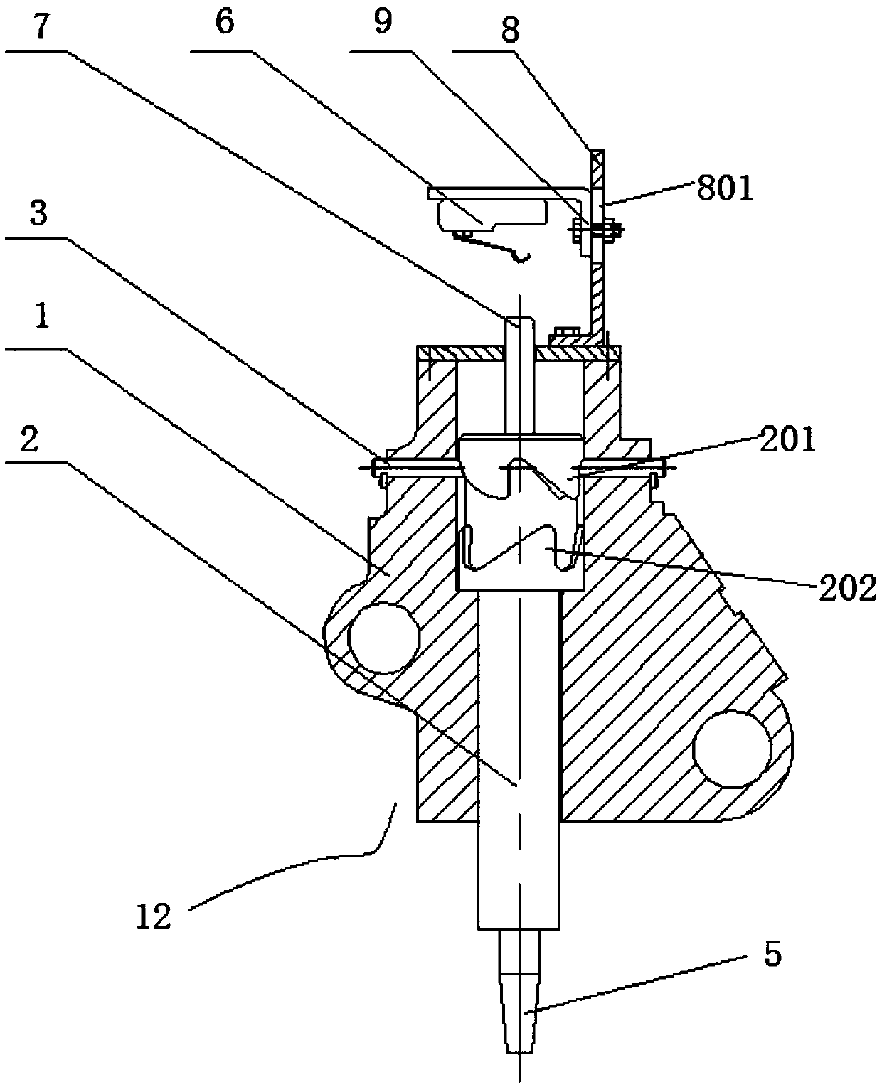
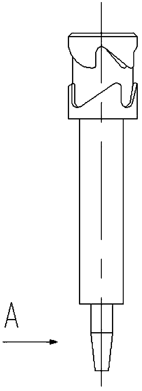
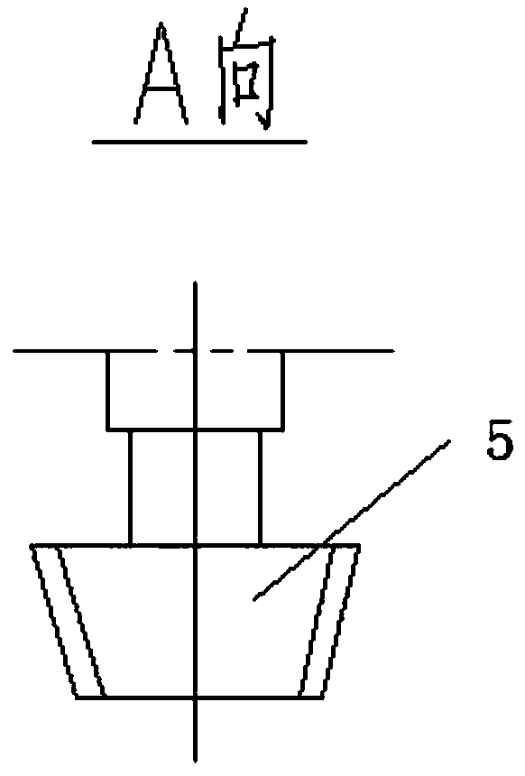
[0028] Such as figure 1 Shown is a rotary trigger device 12 of the present invention, which includes a housing 1, a feeler rod 2, a pin shaft 3, and a lift limit switch 4. The pin shafts 3 in this embodiment are two, which are symmetrically arranged on both sides of the feeler rod . The contact rod 2 is slidingly connected with the housing 1, the upper part of the contact rod 2 is provided with an upwardly inclined groove 201 and a downwardly inclined groove 202 arranged in dislocation, the lower part of the contact rod is provided with a contact 5, and the pin shaft One end of 3 is fixed on the housing 1, and the other end is located between the upward slope groove 201 and the downward slope groove 202. The lifting limit switch 4 is arranged below the contact 5, and the pin shaft 3 is connected to the housing 1 together. Lifting, driving...


PUM


Abstract

The invention discloses a rotary triggering device and a vertical intelligent steel roll clamp. A shell, a trigger rod, a pin shaft and a lifting limiting switch are included, the trigger rod is in sliding connection with the shell, an upper slope groove and a lower slope groove which are arranged in a misplacement manner are arranged at the upper portion of the trigger rod, a contact is arranged at the lower portion of the trigger rod, the contact is arranged at the lower portion of the trigger rod, one end of the pin shaft is fixed to the shell, and the other end of the pin shaft is located between the upper slope groove and the lower slope groove; the lifting limiting switch is arranged below the contact, the pin shaft and the shell are connected and are lifted together, the trigger rod is driven to rotate, and therefore the contact is avoided from or is in contact with the lifting limiting switch. The clamp comprises the rotary triggering device, a clamp body and a coder. By means of the vertical intelligent steel roll clamp, an adjustable final motion mechanical limiting switch is adopted for accurately positioning the contact lifting stroke of the clamp, a control signal that the clamp has descended to be in place is provided for a control system, and automatic clamping and unrolling can be achieved.

Description

technical field [0001] The invention belongs to the technical field of unmanned intelligent hoisting of steel coil warehouses, and in particular relates to a rotary trigger device and a vertical intelligent steel coil clamp. Background technique [0002] With the progress and development of society, modern control technology is more and more integrated into modern production technology. Due to its advantages of high efficiency, safety and economy, the unmanned intelligent crane control system has been more and more used in warehouses. in the scheduling system. [0003] At present, domestic horizontal steel coil unmanned hoisting technology has been applied, and the effect is remarkable. However, for the lifting of vertical steel coils, due to the purely mechanical structure, it is impossible to provide corresponding control signals for the control system; at the same time, the vertical steel coil clamps have a large impact force during use, and the lifting speed of the clam...

Claims


Application Information

Patent Timeline
Patent Type & Authority Patents(China)
IPC IPC(8): B66C1/44B66C13/16B66C13/50B66C15/06
CPCB66C1/44B66C13/16B66C13/50B66C15/06
Inventor 高爱民
Owner CISDI RES & DEV CO LTD
Why Eureka
Try Eureka