Fuel gas heat energy power system based on pressurizing condensation

A power system and gas technology, applied in the direction of machines/engines, steam engine devices, mechanical equipment, etc., can solve the problems of large heat energy waste, small external waste heat absorption rate, unstable gasification temperature of working fluid, etc., and achieve stable gasification temperature and working medium flow rate, improve gasification efficiency and condensation efficiency, and avoid the effect of unstable turbine speed

Inactive Publication Date: 2017-02-22
郭远军
View PDF0 Cites 0 Cited by
  • Summary
  • Abstract
  • Description
  • Claims
  • Application Information

AI Technical Summary

Problems solved by technology

[0007] However, the common problems of existing thermal power generation equipment are: a. The temperature requirements for high-temperature heat sources are high, generally above 200°C, and the thermal energy conversion efficiency is low, and the thermal energy conversion efficiency is generally 15% to 35%; b. The heat displacement of the condensing device is large, and the waste of heat energy is large. The condensation speed through the natural condensation method is slow, and the active condensation method (fan air cooling or liquid pump water cooling) requires additional power consumption; c. The turbine is prone to leakage of working fluid Problems; d. Turbine speed is unstable, and it is prone to stuck problems; e. The heat collection effect of the heat collector is not good, and the external waste heat absorption rate is small; f. The gasification temperature of the working medium is unstable, and the condensation effect of the working medium is not good , the working medium is easy to deteriorate or appear impurities; g. The existing equipment is relatively large

Method used


Image

  • Fuel gas heat energy power system based on pressurizing condensation
  • Fuel gas heat energy power system based on pressurizing condensation
  • Fuel gas heat energy power system based on pressurizing condensation

Examples


Embodiment 1

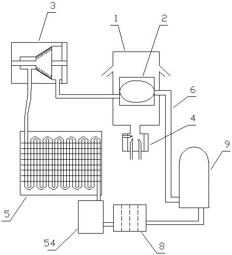
[0080] Embodiment one (such as figure 1 Shown): a gas thermal power system based on pressurized condensation, including a heat collector 1, a gasification device 2, a turbine 3, a gas heating furnace 4, a condensing device 5, a circulation pipeline 6, a circulating working medium 7 and a unit The hydraulic pump 9, the gasification device 2, the turbine 3, the condensing device 5 and the one-way hydraulic pump 9 realize circulation through the circulation pipeline 6 in sequence. The circulation pipeline 6 contains a circulating working medium 7, and the heat collection device 1 is installed 2 outside, used for gasification heating of working fluid in gasification device 2;

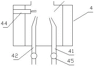
[0081] (Such as figure 2 As shown), the gas heating furnace 4 includes a gas inlet 41, an air inlet 42, a mixed gas combustion chamber 43 and an igniter 44, the hot gas outlet of the mixed gas combustion chamber 43 is connected to the heat collector 1, and the gas inlet 41 and the air inlet 42 are both A...

Embodiment 2

[0091] Embodiment two (such as Figure 6 Shown): The difference from Embodiment 1 is that the heat collecting device 1 includes an upper cover 11 and a lower cover 12, a heating port 13 is provided in the middle of the lower cover 12, and the upper cover 11 and the lower cover 12 are respectively located on the upper and lower sides. Between 11 and the lower cover 12 is a heat collecting chamber 14, two layers of upper cover protruding rings 111 are distributed on the lower part of the upper cover 11 of the heat collecting device 1, and two layers of lower cover protruding rings 121 are distributed on the upper part of the lower cover 12 of the heat collecting device 1, The protruding ring 111 of the upper cover and the protruding ring 121 of the lower cover are staggered.

[0092] By conducting experiments on the gas thermal energy power system based on pressurized condensation in the above-mentioned embodiment 2, gas is introduced into the gas heating furnace 4, and the com...

Embodiment 3

[0093] Embodiment three (such as Figure 7 Shown): The difference from Embodiment 1 is that the lower part of the upper cover 11 of the heat collecting device 1 is provided with a three-layer upper cover protruding ring 111, and the upper part of the lower cover 12 of the heat collecting device 1 is distributed with a three-layer lower cover protruding ring 121 , the upper cover protruding ring 111 and the lower cover protruding ring 121 are staggered.

[0094] By conducting experiments on the gas thermal power system based on pressurized condensation in the above-mentioned embodiment three, gas is fed into the gas heating furnace 4, and the combustion temperatures in the gas heating furnace 4 are respectively 120°C, 150°C, 200°C, 250°C, 300°C, 400°C, the flow rate of the working medium in the circulation pipe is adjusted according to the operation stability of the gas thermal energy power system based on pressurized condensation; the experimental results are: the combustion ...


PUM

PropertyMeasurementUnit
Boiling pointaaaaaaaaaa

Abstract

The invention discloses a fuel gas heat energy power system based on pressurizing condensation. The fuel gas heat energy power system comprises a gasification device, a turbine, a condensing unit and a one-way hydraulic pump which circularly communicate with one another sequentially through circulating pipelines. The circulating pipelines internally contain a circulating working medium. A heat collection device is installed outside the gasification device and communicates with a fuel gas heat supplying furnace. The fuel gas heat supplying furnace comprises a fuel gas inlet, an air inlet, a mixed gas combustion chamber and an igniter. The condensing unit comprises a condenser pipe, a heat dissipation fan and a pressurizing mechanism. The pressurizing mechanism is installed at the middle end of the condenser pipe. The pressurizing mechanism comprises a pressurizing turbine and a turbine pressure regulator, and the turbine pressure regulator is connected with the pressurizing turbine in a control manner. The fuel gas heat energy power system based on pressurizing condensation has a high condensing rate, can reduce the condensing exhaust energy and improve the heat energy conversion efficiency and is stable in running and adjustable in power.

Description

technical field [0001] The invention belongs to the field of energy utilization equipment, in particular to a gas heat energy power system based on pressurized condensation. Background technique [0002] Energy is an important material basis for the survival and development of human society. Throughout the history of the development of human society, every major progress of human civilization is accompanied by the improvement and replacement of energy. The development and utilization of energy has greatly promoted the development of the world economy and human society. [0003] However, with the continuous development and consumption of energy, non-renewable energy sources such as petroleum, coal mines, and natural gas are gradually reduced, and energy conservation and recycling are gradually being valued. The basic content of my country's current energy strategy is: adhere to the priority of conservation, based on domestic, diversified development, rely on science and tec...

Claims


Application Information

Patent Timeline
IPC IPC(8): F01K11/02F01K27/02
CPCF01K11/02F01K27/02
Inventor 郭远军
Owner 郭远军
Why Eureka
Try Eureka