Working medium circulation condensation heat energy power system utilizing heat water drainage of nuclear power station

A technology of working medium circulation and power system, which is applied in the direction of machines/engines, steam engine devices, mechanical equipment, etc., can solve the problems of high exhaust port pressure, small external waste heat absorption rate, and small output power of thermal energy generators, etc., to achieve reduction Effects of heat energy waste and cooling energy consumption, improvement of gasification efficiency and condensation efficiency, stabilization of gasification temperature and working medium flow rate

Inactive Publication Date: 2016-12-14
郭远军
View PDF0 Cites 0 Cited by
  • Summary
  • Abstract
  • Description
  • Claims
  • Application Information

AI Technical Summary

Problems solved by technology

[0007] However, the common problems of existing thermal power generation equipment are: a. The temperature at the exhaust port of the turbine is relatively high, resulting in high pressure at the exhaust port, and the work conversion efficiency of the turbine is low; b. The heat displacement of the condensing device is relatively large , the waste of heat energy is large, the condensation speed through natural condensation is slow, and the active condensation method (fan air cooling or liquid pump water cooling) requires additional power consumption; c. The temperature requirements for high-temperature heat sources are high, generally above 200 ° C, and The thermal energy conversion efficiency is low, and the thermal energy conversion efficiency is generally 15% to 35%; d. Gasification heat absorption is slow, and the output power of the thermal energy machine is relatively small; e. The heat collection effect of the heat collection device is not good, and the external waste heat absorption rate is small , f. The gasification temperature of the working fluid is unstable, the condensation effect of the working fluid is not good, and the working fluid is easy to deteriorate or appear impurities
[0009] However, the development of nuclear power has also brought great concerns to people, because the construction and use of nuclear power plants will not only cause certain radioactive pollution to the environment, but also cause high-temperature pollution to nearby waters.
Nuclear power plants need a large amount of water to cool the reactor. A nuclear power plant consumes hundreds of tons of water per second. Cold sea water or river water is discharged back into the sea after heat exchange in the plant. The temperature of the water will rise by 20 to 30 degrees. After the drain is discharged, the temperature of the water within a radius of 1 km can rise as high as 5°C to 8°C. When the temperature of cold sea water or river water reaches 30°C in summer, after absorbing the heat exhausted by the nuclear power plant, the temperature can rise by about 40°C. , the general fish and seaweed organisms cannot survive, and it also brings a greater impact of high temperature on nearby residents
[0010] As for the thermal energy in the thermal drainage of the above-mentioned nuclear power plant, since the temperature difference between the thermal drainage and normal temperature water is only about 20°C, this temperature difference is difficult to be utilized by existing thermal power generation equipment

Method used


Image

  • Working medium circulation condensation heat energy power system utilizing heat water drainage of nuclear power station
  • Working medium circulation condensation heat energy power system utilizing heat water drainage of nuclear power station
  • Working medium circulation condensation heat energy power system utilizing heat water drainage of nuclear power station

Examples


Embodiment 1

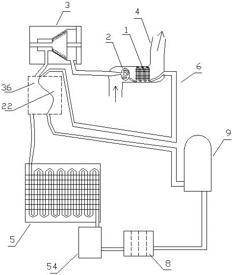
[0079] Embodiment one (such as figure 1 Shown): a working medium circulation condensation heat energy power system utilizing thermal drainage of a nuclear power plant, including a heat collector 1, a gasification device 2, a turbine 3, a nuclear power plant thermal drain 4, a condensing device 5, a circulating pipeline 6, and a circulating working medium 7 and one-way hydraulic pump 9, heat collector 1, gasification device 2, turbine 3, condensing device 5 and one-way hydraulic pump 9 realize circulation communication through circulation pipeline 6 in sequence, and circulation pipeline 6 contains circulating working fluid 7, and Gasification heating of working fluid in the gasification device 2;

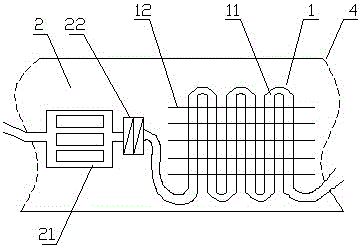
[0080] (Such as figure 2 As shown), the heat collection device 1 and the gasification device 2 are installed in the thermal drain 4 of the nuclear power plant, and the condensation device 5 is installed in the deep water low temperature area. The heat sinks 12 are distributed in p...

Embodiment 2

[0093] Embodiment two (such as Image 6 shown): The difference from Embodiment 1 is that the heat collecting sheet 12 of the heat collecting device 1 is in the shape of a curved sheet.

[0094] By conducting experiments on the working medium circulation condensing heat energy power system using thermal drainage of nuclear power plants in the above-mentioned embodiment 2, hot water of different temperatures is discharged into the heat collection device 1 and the gasification device 2, the temperature of the cold source is 10 ° C, and the drainage rate is 3000L / s, the flow rate of the working medium in the circulation pipe is adjusted according to the operation stability of the working medium circulation condensation heat power system using the thermal drainage of the nuclear power plant; the experimental results are: when the temperature of the hot water is about 40°C, the heat conversion efficiency is about 17.5%, When the hot water temperature is about 45°C, the thermal ener...

Embodiment 3

[0095] Embodiment three (such as Figure 7 shown): The difference from Embodiment 1 is that the heat collecting fins 12 of the heat collecting device 1 are distributed in a staggered manner.

[0096] By conducting experiments on the working medium circulation condensing heat energy power system using thermal drainage of nuclear power plants in the above-mentioned embodiment three, hot water of different temperatures is discharged into the heat collector 1 and the gasification device 2, the temperature of the cold source is 10 ° C, and the drainage rate is 3000L / s, the flow rate of the working medium in the circulation pipe is adjusted according to the operation stability of the working medium circulation condensation heat power system using the thermal drainage of the nuclear power plant; the experimental results are: when the temperature of the hot water is about 40°C, the heat conversion efficiency is about 17.5%, When the hot water temperature is about 45°C, the thermal en...


PUM


Abstract

The invention discloses a working medium circulation condensation heat energy power system utilizing heat water drainage of a nuclear power station. The working medium circulation condensation heat energy power system comprises a heat collection device, a gasification device, a turbine, a condensation device and a one-way hydraulic pump which are sequentially in circulation communication through a circulation pipeline. A circulation working medium is included in the circulation pipeline. The heat collection device and the gasification device are mounted in a heat water drainage channel of the nuclear power station. The condensation device is mounted in a deep water low-temperature area. The gasification device comprises a gasification heat absorption cavity and a preheating cavity pipe. A pre-condensation cavity is formed in an exhaust opening of the turbine, and the preheating cavity pipe and the pre-condensation cavity are in parallel contact. According to the working medium circulation condensation heat energy power system utilizing heat water drainage of the nuclear power station, condensation can be accelerated, the efficiency of the turbine can be improved, the discharge amount of heat energy can be reduced, and therefore the conversion efficiency of the heat energy is improved.

Description

technical field [0001] The invention belongs to the field of energy utilization equipment, in particular to a working fluid circulation condensing thermal energy power system utilizing thermal drainage of a nuclear power plant. Background technique [0002] Energy is an important material basis for the survival and development of human society. Throughout the history of the development of human society, every major progress of human civilization is accompanied by the improvement and replacement of energy. The development and utilization of energy has greatly promoted the development of the world economy and human society. [0003] However, with the continuous development and consumption of energy, non-renewable energy sources such as petroleum, coal mines, and natural gas are gradually reduced, and energy conservation and recycling are gradually being valued. The basic content of my country's current energy strategy is: adhere to the priority of conservation, based on dome...

Claims


Application Information

Patent Timeline
Patent Type & Authority Applications(China)
IPC IPC(8): F01K11/02F01K27/02
CPCF01K11/02F01K27/02
Inventor 郭远军
Owner 郭远军
Why Eureka
Try Eureka