Heat energy power system for liquid condensation

A power system and thermal energy technology, applied in steam/steam condensers, machines/engines, lighting and heating equipment, etc., can solve the problems of unstable medium pressure, low conversion efficiency of mechanical energy, and lower maximum efficiency of thermal energy, etc. efficiency and condensation efficiency, improve thermal energy conversion efficiency, and increase the effect of thermal conversion efficiency

Inactive Publication Date: 2017-02-22
郭远军
View PDF0 Cites 0 Cited by
  • Summary
  • Abstract
  • Description
  • Claims
  • Application Information

AI Technical Summary

Problems solved by technology

[0005] The existing thermal energy utilization equipment that uses gas expansion to do work, under ideal conditions, has the highest rate of thermal energy conversion, which is the Carnot cycle efficiency, that is, 1-T 0 / T 1 , where T 0 is the temperature of the cold source, T 1 It is a high-temperature heat source; but in the actual work process of thermal equipment, on the one hand, due to the gasification process of the circulating working fluid in the gasification device, the actual temperature of its gasification expansion has a large temperature difference with the temperature of the high-temperature heat source, and the actual temperature is lower than the temperature of the high-temperature heat source , whose theoretical T 1 On the other hand, because the actual condensation temperature of the circulating working fluid in the condenser is higher than the temperature of the low-temperature cold source, its theoretical T 0 increase, leading to a decrease in the maximum efficiency of thermal energy; in addition, due to the low absorption rate of the turbine for gas expansion work, its mechanical energy conversion efficiency is low; in addition, the circulating working fluid is prone to impurities, and the circulating working medium consumes a lot of energy
[0006] The specific problems caused by the above-mentioned deviations in existing thermal energy equipment include: 1. The thermal conductivity of the gasification device is poor, and the temperature requirements for high-temperature heat sources are high; 2. The pressure of the gasification device is unstable, and the temperature required for gasification is unstable , when the temperature required for gasification is greater than the temperature of the heat source, the medium cannot be vaporized; when the temperature required for gasification is lower than the temperature of the heat source, the gasification expansion temperature is low, the heat absorption is small, and the net work is small; 3. Condenser The pressure of the internal medium is unstable, and the temperature required for condensation is unstable. When the temperature required for condensation is lower than the temperature of the cold source, condensation cannot be achieved. When the temperature required for condensation is greater than the temperature of the cold source, the temperature after condensation is too low; 4. Condenser The internal condensation is not complete, and the gas-liquid mixed state is prone to appear, resulting in a relatively small gasification and expansion volume of the working fluid in the gasification device; 5. The existing turbine has a relatively small torque, large volume leakage, and low efficiency; 6. The thermal energy conversion efficiency of existing thermal energy equipment is low, and the thermal energy conversion efficiency is generally 10% to 30%; 7. The working medium is easy to deteriorate or appear impurities

Method used


Image

  • Heat energy power system for liquid condensation
  • Heat energy power system for liquid condensation
  • Heat energy power system for liquid condensation

Examples


Embodiment 1

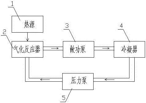
[0098] Embodiment one (such as figure 1 shown): a thermal power system for liquid condensation, including heat source 1, gasification reactor 2, work pump 3, condenser 4, pressure pump 5 and circulation pipeline 6, gasification reactor 2, work pump 3, condensation The device 4 and the pressure pump 5 realize circulation through the circulation pipe 6, and the gasification reactor 2 is in contact with the heat source 1;

[0099] As a specific description of the above implementation process, the heat source 1 adopts medium-high temperature gas.

[0100] As a specific description of the above implementation process, the gasification reactor 2 includes a layer of cavity 21; the cavity 21 is elliptical.

[0101] As a specific description of the above implementation process, the working pump 3 is an impeller working pump.

[0102] As a specific description of the above implementation process, the condenser 4 is an air-cooled condenser.

[0103] As a specific description of the ab...

Embodiment 2

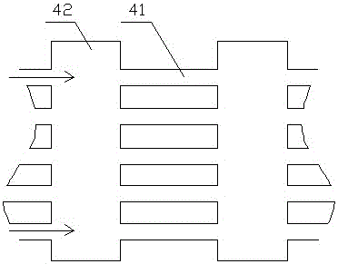
[0106] Embodiment two (such as figure 2 shown): The difference from Embodiment 1 is that the condenser 4 adopts a liquid cooling method, and the condenser 4 includes a condensation pipe 41 and four condensation chambers 42, and multiple condensation pipes are passed between the two condensation chambers 42 The pipe 41 is connected; the condensation pipe 41 is curved; the condensation pipe 41 is spiral.

[0107] With the above-mentioned structure, since the working medium in the condenser 4 undergoes multiple mixing and splitting, and has a large contact area with the outside world, the working medium can be separated from gas and liquid in the condensation chamber 42, which can effectively avoid incomplete condensation and reduce condensation. The pressure of the chamber 42 increases the amount of work done by the work pump 3, and at the same time increases the expansion ratio of the working fluid in the gasification reactor 2, thereby improving efficiency.

[0108]Experimen...

Embodiment 3

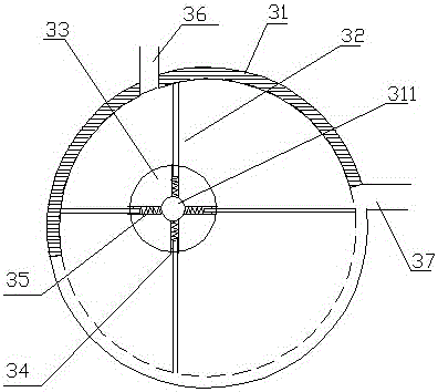
[0109] Embodiment three (such as image 3 shown): The difference from Embodiment 1 is that the working pump 3 includes a circular chamber 31, eccentric blades 32 and a grooved runner 33, and the grooved runner 33 is eccentrically installed on the eccentric shaft 311 of the circular chamber 31 Inside, the side of the grooved runner 33 is provided with a card slot 34, the eccentric blade 32 is installed in the card slot 34 through a spring leaf 35, and the sides of the circular cavity 31 are respectively provided with an air inlet 36 and an air outlet 37, and the air inlet The spacing angle between mouth 36 and air outlet 37 is greater than the spacing angle between adjacent two eccentric blades 32; The pitch angle between two adjacent eccentric blades 32; the eccentric blades 32 of the working pump 3 include four pieces.

[0110] Adopt above-mentioned structure, form isolated chamber between adjacent eccentric blades 32, and what communicate with air inlet 36 is expansion cham...


PUM


Abstract

The invention discloses a heat energy power system for liquid condensation. The heat energy power system for liquid condensation comprises a heat source, a gasification reactor, an acting pump, a condenser, a pressure pump and circulating pipes; the gasification reactor, the acting pump, the condenser and the pressure pump realize circular communication through the circulating pipes; the gasification reactor is contacted with the heat source; the condenser is contacted with liquid condensate, and includes a condensing pipe and multiple condensing cavities; and two condensing cavities are communicated through at least one condensing pipe. The heat energy power system for liquid condensation has the advantages of high condensation liquifying efficiency and high heat energy conversion efficiency.

Description

technical field [0001] The invention belongs to the field of energy utilization equipment, in particular to a thermal energy power system of liquid condensation. Background technique [0002] Energy is an important material basis for the survival and development of human society. Throughout the history of the development of human society, every major progress of human civilization is accompanied by the improvement and replacement of energy. The development and utilization of energy has greatly promoted the development of the world economy and human society. [0003] However, with the continuous development and consumption of energy, non-renewable energy sources such as petroleum, coal mines, and natural gas are gradually reduced, and energy conservation and recycling are gradually being valued. In response to the national energy-saving strategy, more and more enterprises have begun to develop and use energy-saving equipment, and strengthen the utilization of waste energy p...

Claims


Application Information

Patent Timeline
Patent Type & Authority Applications(China)
IPC IPC(8): F01K11/00F01K25/08F01K25/10F01C1/344H02N11/00F28B1/00B01D1/00
CPCF01K11/00B01D1/00F01C1/3446F01K25/08F01K25/10F01K25/106F28B1/00H02N11/002
Inventor 郭远军
Owner 郭远军
Why Eureka
Try Eureka