Top-blown heat pipe radiator and its manufacturing method

A heat pipe radiator, top-blown technology, applied in the direction of cooling/ventilation/heating transformation, equipment, instrument cooling, etc., can solve the problem of not meeting the heat dissipation performance of the radiator, large temperature difference of the radiator, and low heat dissipation efficiency and other issues, to achieve the effect of light weight, large heat dissipation capacity, and improved heat dissipation efficiency

Inactive Publication Date: 2006-03-08
嘉善华昇电子热传科技有限公司
View PDF0 Cites 5 Cited by
  • Summary
  • Abstract
  • Description
  • Claims
  • Application Information

AI Technical Summary

Problems solved by technology

However, due to the large temperature difference along the axial direction of the copper column, the temperature difference between the upper and lower parts of the radiator is relatively large, which reduces the heat dissipation efficiency, reduces the heat dissipation capacity, and has a large thermal resistance, and the copper column is relatively heavy, which cannot meet the high-speed development of electronic components. Demand for heat dissipation performance of radiators

Method used


Image

  • Top-blown heat pipe radiator and its manufacturing method
  • Top-blown heat pipe radiator and its manufacturing method
  • Top-blown heat pipe radiator and its manufacturing method

Examples


Embodiment Construction

[0019] The present invention will be further explained below in conjunction with the drawings:

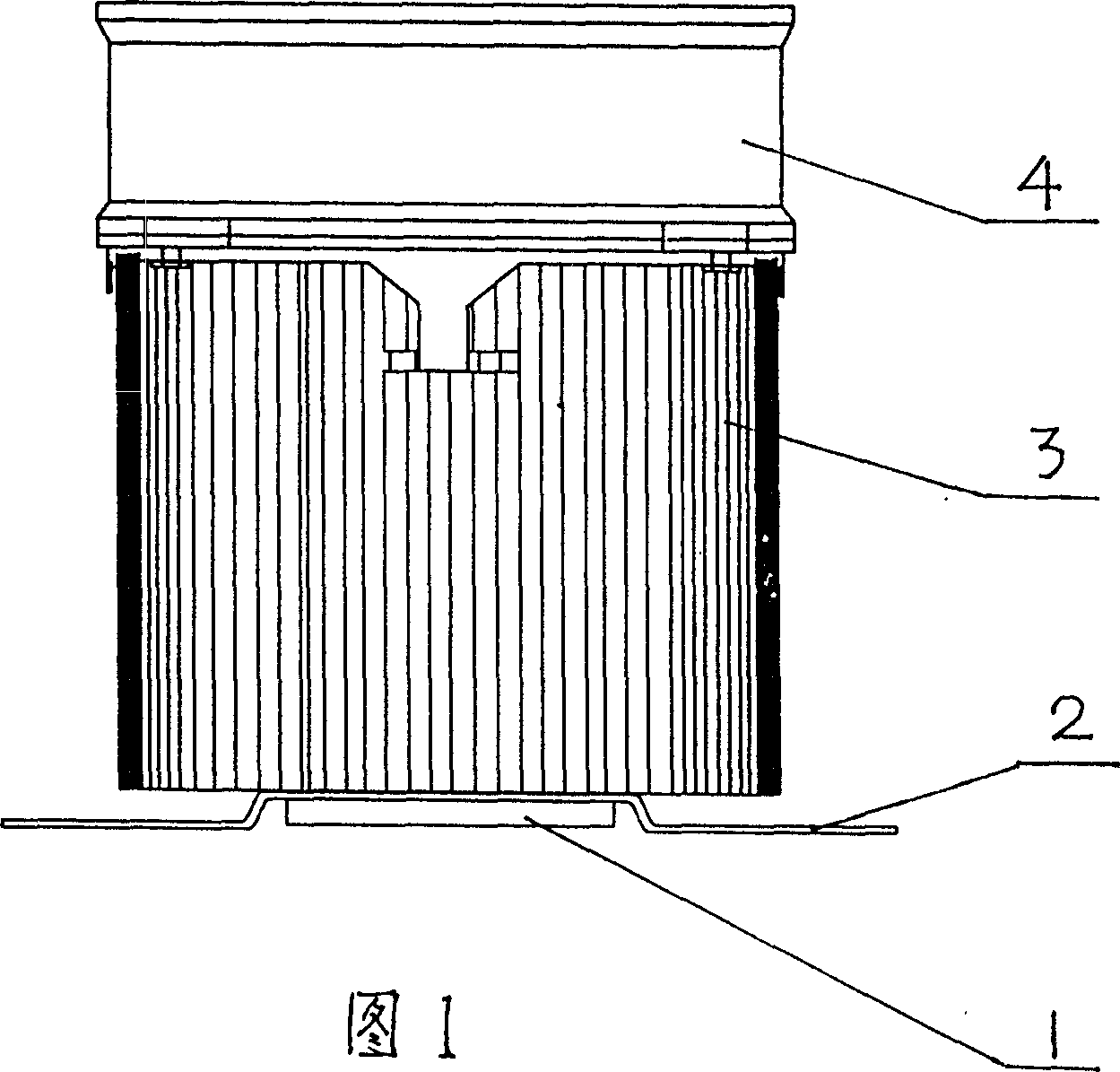
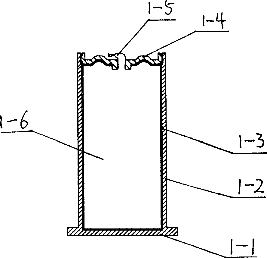
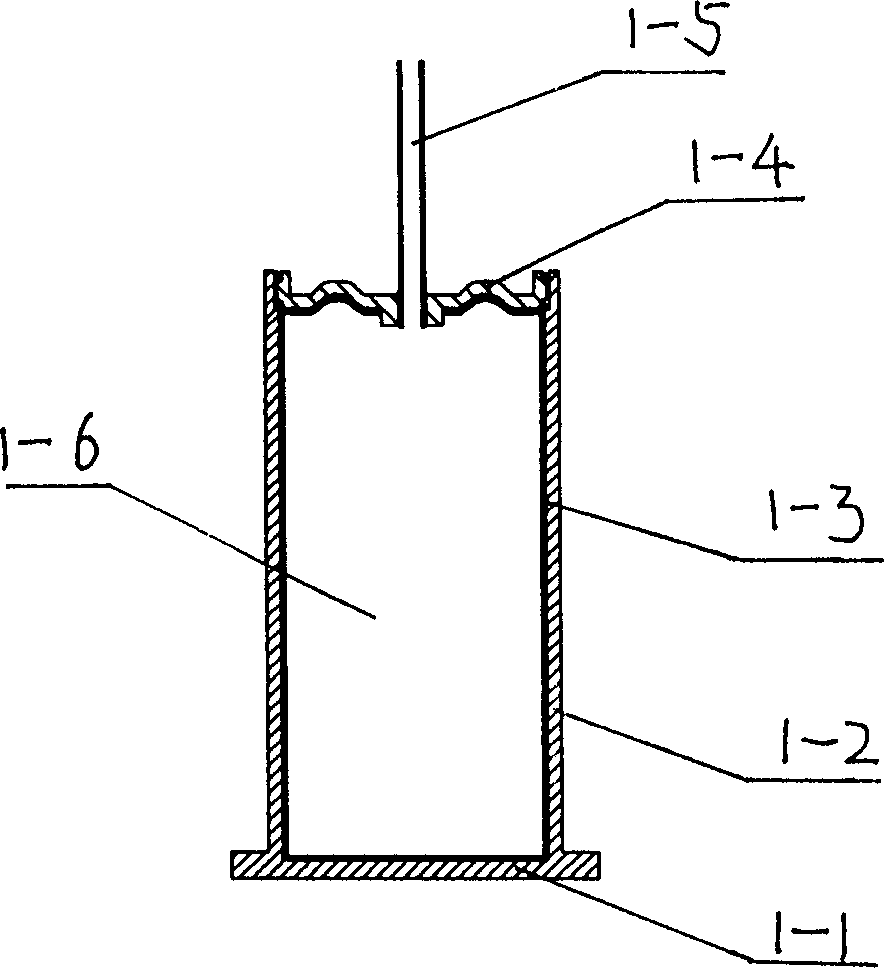
[0020] Refer to Figure 1, Figure 6 , Figure 8 , This top-blowing heat pipe radiator includes a heat pipe 1, a fastener 2, a heat sink base 3 and a fan 4. The heat sink base 3 has a through hole 3-1 penetrating up and down and a plurality of radiating fins 3-2. The heat pipe 1 is composed of a bottom plate 1-1, a pipe body 1-2, a top cover 1-4, and an exhaust pipe 1-5 to form a sealed cavity 1-6, and the inside is vacuum. The inner surface of the sealed cavity 1-6 is provided with a sintered layer 1-3 with a porous capillary structure. The sintered layer 1-3 is made by sintering copper powder at a high temperature, and the sintered layer 1-3 adsorbs working fluid; the bottom plate 1-1 Set at the lower end of the tube body 1-2, the upper end of the tube body 1-2 is provided with a top cover 1-4, and the top cover 1-4 is provided with an exhaust pipe 1-5, through the exhaust pipe 1-5 to...


PUM


Abstract

The radiator includes heat pipe, basal body of thermal fin, and fan. There are through holes inside basal body of thermal fin, and heat pipes are setup in through holes. Inner diameter of through hole is close fitted to external diameter of heat pipe. Multiple radial thermal fins are setup around. Being setup on top of basal body of thermal fin, fan is in use for forcing air to pass through radial thermal fins from upper to lower. Being in mode of evaporation condensed phase change, heat pipe conducts heat, providing features of quick conduction rate, large heat transfer power. Multiple radial thermal fins possess large area of dissipation. Forced air driven by fan passes through radial thermal fins in small wind resistance. Features of the invention are: large heat sinking capability, small thermal resistance, and lightweight.

Description

Technical field [0001] The invention relates to a heat dissipation device, in particular to a top-blowing type heat pipe radiator for heating electronic components (including a personal computer CPU) and a manufacturing method. Background technique [0002] At present, a widely used electronic component radiator is an aluminum extruded sunflower radiator. The radiating fins are distributed radially outwards along the axial direction. The center is a hole through up and down, and a solid or hollow hole is arranged in the center hole. Copper pillar. The heating surface of the electronic component is directly in contact with the bottom surface of the copper column, and the heat generated during the operation of the electronic component is transferred to the aluminum heat sink by the heat conduction of the copper column, and the fan forces the air to flow through the heat sink to dissipate the heat into the air. [0003] Because the center of the radiator is a copper column with good...

Claims


Application Information

Patent Timeline
Patent Type & Authority Applications(China)
IPC IPC(8): H05K7/20G06F1/20H01L23/36G12B15/00
Inventor 仝爱星王占篱杨互助
Owner 嘉善华昇电子热传科技有限公司
Why Eureka
Try Eureka