
Air conditioner for vehicle

Pending Publication Date: 2022-07-07
HANON SYST
View PDF5 Cites 0 Cited by
  • Summary
  • Abstract
  • Description
  • Claims
  • Application Information

AI Technical Summary

Benefits of technology

The present invention is an air conditioner for a vehicle that has several technical effects. Firstly, it increases the volume of air by preventing air from colliding with each other. Secondly, it is easy to manufacture and assemble due to its optimized form and position. Thirdly, it reduces the temperature difference between the top and bottom of the vehicle when in floor mode, improves mixing performance between cold and warm air, and enhances the dynamic stiffness of the air conditioning case.

Problems solved by technology

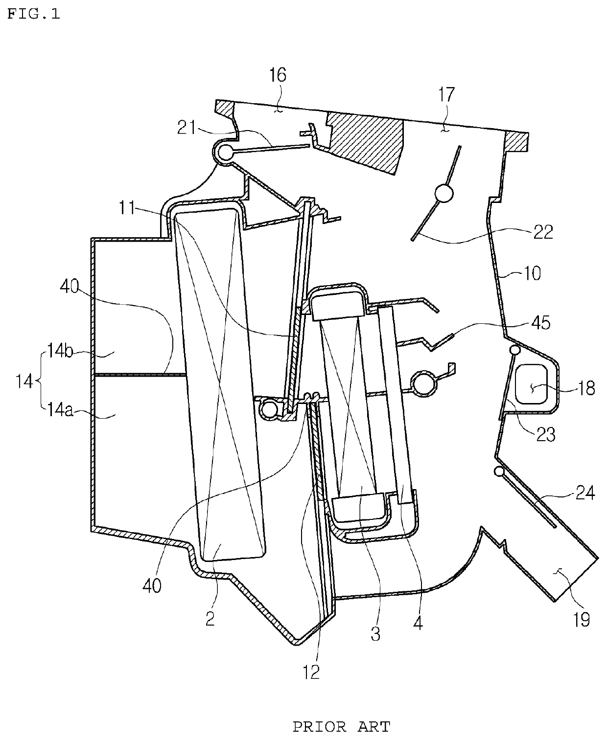
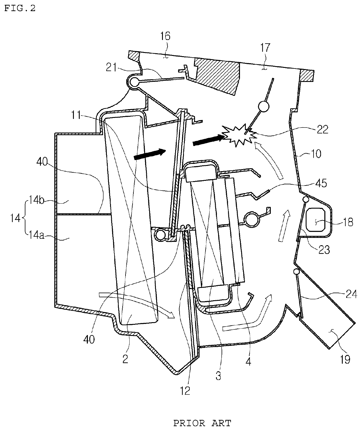
In order to defrost windshields while driving with heat in winter, cold outdoor air with low humidity is effective, but it causes drop of indoor temperature.
So, the conventional two-layer air condition for a vehicle has a disadvantage in that the air volume is decreased because of an increase of resistance.
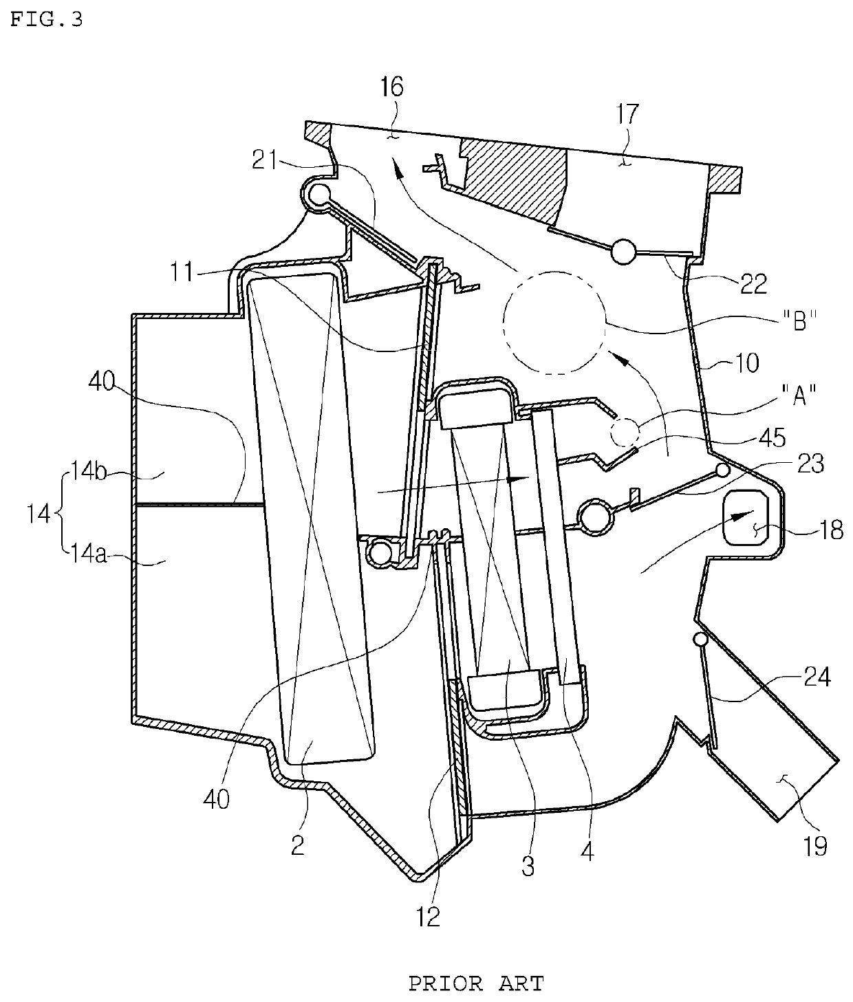
Finally, the conventional two-layer air conditioner for a vehicle has another disadvantage in that there is an excessive top and bottom temperature difference in the temperature evaluation of the floor mode.

Method used


Image

  • Air conditioner for vehicle
  • Air conditioner for vehicle
  • Air conditioner for vehicle

Examples


Embodiment Construction

[0052]Hereinafter, an air conditioner for a vehicle according to preferred embodiments of the present invention will now be described in detail with reference to the attached drawings.

[0053]FIG. 4 is a sectional view illustrating a two-layer air conditioner for a vehicle according to a first preferred embodiment of the present invention, FIGS. 5 and 6 are enlarged sectional views of a guide unit according to the first preferred embodiment of the present invention, FIG. 7 illustrates an air volume evaluation result of a two-layer air conditioner for a vehicle to which the guide unit is not applied, FIG. 8 illustrates an air volume evaluation result of the two-layer air conditioner for a vehicle according to the first preferred embodiment of the present invention, to which the guide unit is applied, and FIG. 9 is a view illustrating a modification of FIG. 4.

[0054]In the description of the present invention, the right-and-left direction of FIG. 4 is the back-and-forth direction of the ...


PUM


Abstract

Disclosed is an air conditioner for a vehicle, the air conditioner having an improved guide structure capable of increasing an air volume by preventing a collision between air flowing through an upper passage and air flowing through a lower passage. The air conditioner for a vehicle comprises: an air conditioning case having an air passage formed therein and an air outlet which includes a defrost vent and a face vent; and a heat exchanger for cooling and a heat exchanger for heating, which are provided in the air passage of the air conditioning case. The air conditioner for the vehicle further comprises: a temperature door arranged between the heat exchanger for cooling and the heat exchanger for heating in order to adjust the degree to which cold air, which has passed through the heat exchanger for cooling, is heated by the heat exchanger for heating; a cold air passage through which cold air that has passed through the heat exchanger for cooling bypasses the heat exchanger for heating; a warm air passage through which cold air that has passed through the heat exchanger for cooling passes through the heat exchanger for heating; a cold air guide unit for guiding the cold air downstream of the heat exchanger for cooling; and a warm air guide unit for guiding the warm air downstream of the heat exchanger for heating.

Description

TECHNICAL FIELD[0001]The present invention relates to an air conditioner for a vehicle, and more particularly, to a two-layer air conditioner for a vehicle, which can secure defogging performance and maintain a high-performance heating during heating.BACKGROUND ART[0002]In general, an air conditioner for a vehicle is an apparatus for cooling or heating the interior of the vehicle by cooling or heating through the process of introducing outdoor air into the interior of the vehicle or circulating indoor air of the vehicle. Such an air conditioner for a vehicle includes an evaporator for a cooling action and a heater core for a heating action inside an air-conditioning case, and selectively blows the air cooled by the evaporator or heated by the heater core toward parts of the interior of the vehicle.[0003]Especially, in order to secure defogging performance and maintain a high-performance heating during heating, a two-layer air conditioner has been developed. In order to defrost winds...

Claims


Application Information

Patent Timeline
IPC IPC(8): B60H1/00
CPCB60H1/00842B60H1/00521B60H2001/00092B60H2001/00135B60H1/00664B60H1/00671B60H2001/00721B60H2001/00164B60H2001/002B60H1/00021B60H1/00692
Inventor LEE, NAM JUNKIM, DONG GYUNKIM, SI HYUNGPARK, DAE KEUNBAE, EUN SUKSEO, JUN HOLEE, HOJO, SEUNG WOO
Owner HANON SYST
Learn More