
Energy saving kiln for preventing ash contamination and with low heat storage

A kiln and heat storage technology, applied in furnaces, furnace types, waste heat treatment, etc., can solve the problems of over-burning color difference of upper products, raw burning of bottom products, unreasonable smoke exhaust structure, etc., to achieve less heat storage, kiln body well-structured effect

Active Publication Date: 2017-09-05
DLT TECH CO LTD
View PDF7 Cites 0 Cited by
  • Summary
  • Abstract
  • Description
  • Claims
  • Application Information

AI Technical Summary

Problems solved by technology

Furthermore, after using for a period of time, these fiber cottons are easy to pulverize, and there will be "powder falling" from time to time
In the high-fire heat preservation stage, the glaze layer (some colored glaze) used for decoration on the surface of the green body is in a molten state, and these long fibers or fiber powder will melt with the glaze layer. Burrs, pinholes, stains and other dirty defects will affect the appearance and image, resulting in product degradation or even scrapping
[0005] (2) Unreasonable smoke exhaust structure
[0006] Because it is difficult to open holes or reserve holes in the wall of fiber cotton, the shuttle kiln with traditional cotton structure generally adopts the method of direct smoke exhaust from the top, but it is easy to cause fire leakage on the top of the kiln.
The temperature difference in the kiln is also increased due to the smoke exhaust from the top, and there are often problems such as raw burning of the bottom product, over-burning of the upper product, and large color difference.

Method used


Image

  • Energy saving kiln for preventing ash contamination and with low heat storage
  • Energy saving kiln for preventing ash contamination and with low heat storage
  • Energy saving kiln for preventing ash contamination and with low heat storage

Examples


Embodiment Construction

[0031] In order to make the object, technical solution and advantages of the present invention clearer, the present invention will be further described in detail below in conjunction with the accompanying drawings. It is only stated here that the words for directions such as up, down, left, right, front, back, inside, and outside that appear or will appear in the text of the present invention are only based on the accompanying drawings of the present invention, and are not specific to the present invention. limited.

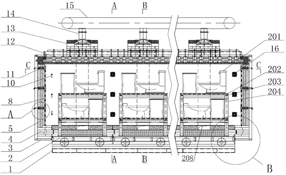
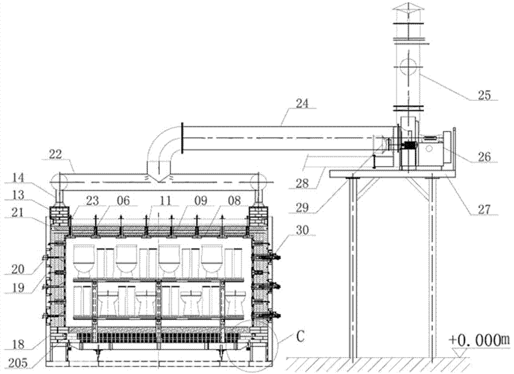
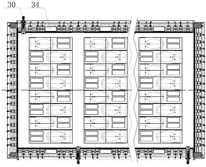
[0032] Such as figure 1 , figure 2 As shown, the embodiment of the present invention provides an energy-saving kiln with anti-staining and less heat storage, including:

[0033] Kiln door 3, kiln roof 12, side wall 19 and multiple kiln cars 2 at the bottom form a shuttle kiln, forming a sealed kiln body structure with fire-resistant and heat-preserving functions, and all of them are installed on the base 1.

[0034] The kiln door 3 and the side wall 19 are co...


PUM


Abstract

The invention discloses an energy saving kiln for preventing ash contamination and with low heat storage. The kiln comprises a kiln door, a kiln crown and side walls, and is characterized in that light insulation cottons are arranged on the kiln door, the kiln crown and the side walls; heavy refractory insulation plates are arranged on a fire seeing surface in the kiln; the refractory insulation plates adopt hollow structures, and are formed by splicing insulation plates; heavy refractory guide rails are arranged between upper and lower adjacent insulation plates; the insulation plates are inserted in chucks on the upper and lower sides of the refractory guide rails; and refractory fixed pieces connected with a kiln body are arranged at the middle parts of the refractory guide rails. The kiln crown, the kiln walls and the kiln door adopt all-cotton structures; the heavy refractory insulation plates are added on the internal fire seeing surface and the tabletop of a kiln car insulated by light materials at the bottom for preventing direct scouring of the wall fiber cottons by flame. Thus, even if fibers are pulverized and loosened to fall, due to stop by the refractory plates, products cannot be polluted. The kiln saves the energy, and solves the ash contamination problem.

Description

technical field [0001] The present invention relates to an energy-saving kiln that is anti-dirty and has less heat storage, and is mainly used for firing ceramic products at high temperatures. Background technique [0002] Ceramic products are sintered at high temperature in a kiln. In order to reduce the unit energy consumption of ceramic products in the firing process, people in the industry have carried out a lot of research and exploration work, and have made great progress. The structure of the shuttle kiln that uses light refractory and thermal insulation fiber blankets is a typical representative, and the energy saving effect is quite obvious. But there are the following problems: [0003] (1) dirty [0004] Aluminum silicate fiber blankets have good heat preservation, but because of their low bulk density and light specific gravity, when the gas flow in the kiln is fast, the loose fibers will be disturbed to make them fall off and fall onto the green body. Furthe...

Claims


Application Information

Patent Timeline
Patent Type & Authority Applications(China)
IPC IPC(8): F27B9/26F27B9/30F27D17/00
CPCF27B9/262F27B9/30F27D17/004Y02P40/60
Inventor 熊亮祝守焱荆海山曾磊余晓俊
Owner DLT TECH CO LTD
Learn More