Sewing machine

A technology for sewing machines and sewing needles, which is applied to sewing machine components, sewing equipment, cloth feeding mechanisms, etc., and can solve problems such as thread slack, hard-to-feed tooth changes, and presser foot elevation

Inactive Publication Date: 2017-10-20
JUKI CORP
View PDF8 Cites 14 Cited by
  • Summary
  • Abstract
  • Description
  • Claims
  • Application Information

AI Technical Summary

Problems solved by technology

[0007] However, in the conventional sewing machine in which the cloth is fed by sandwiching the cloth with the presser foot and the feed teeth, there is a problem that the presser foot rises and the pressure of the presser foot decreases at the step where the cloth becomes thicker.
[0008] At this time, if the height of the feed tooth is further increased, the gap between the presser foot and the presser foot becomes smaller, so the decrease in the pressure of the presser foot can be compensated. In the feed mechanism of the moving feed teeth, it is difficult to change the height of the feed teeth during the rotation of the main shaft
[0009] In addition, in the presser foot lifting mechanism such as Patent Document 2, since a solenoid is used as a driving source for the raising motion of the cloth presser foot, it is difficult to arbitrarily adjust the presser foot pressure of the cloth presser foot through control.
[0010] In addition, if the presser foot jumps up the step, there is also a problem of thread slack

Method used


Image

  • Sewing machine
  • Sewing machine
  • Sewing machine

Examples


Embodiment Construction

[0085] [Schematic structure of the embodiment]

[0086] Next, a sewing machine as an embodiment of the present invention will be described in detail.

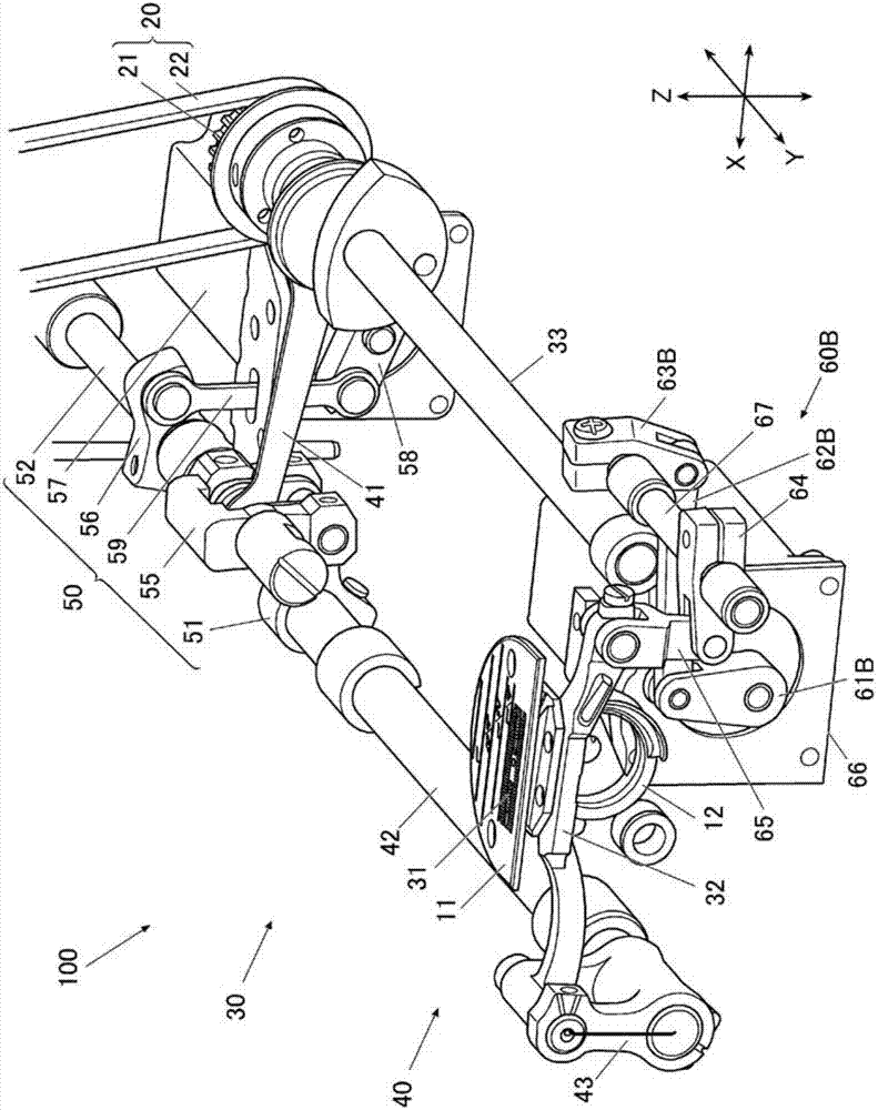
[0087] figure 1 It is a perspective view which shows the main structure inside the sewing machine base part of the sewing machine 100. FIG.

[0088] Such as figure 1 As shown, the sewing machine 100 has: a sewing needle up and down movement mechanism not shown in the figure, which moves the sewing needle up and down; the sewing machine motor 16 (refer to Figure 13 ), which becomes the driving source of the sewing needle up and down movement mechanism; the upper shaft not shown in the figure, which is rotated by the sewing machine motor 16; the kettle 12, which winds the upper thread and the lower thread; The up and down movement of the needle plate 11 correspondingly conveys the cloth as the object to be sewn; the transmission belt mechanism 20 transmits the rotational force from the upper shaft 33 of the feed device 30; th...


PUM


Abstract

Parameters, such as the amount of up-and-down sending after a to-be-sewed objects detect a step which becomes thick, press pin pressure and thread tension, can be changed. A sewing machine includes: a cloth press pin (71), which presses a sewed object from above; a press pin height detection unit (76), which detects the height of the cloth press pin (71); and a control device (90), which plays a control role if the press pin height detection unit (76) detects that the cloth press pin (71) jumps on the step thicked by the sewed object so as to change parameters associated with sewing. For instance, if the press pin height detection unit (76) detects that the cloth press pin (71) jumps on the step, the control device (90) controls an up-and-down feeding motor (66) applying upward and downward reciprocating movement to feeding teeth (31) to raise the feeding teeth (31) in a feeding interval.

Description

technical field [0001] The invention relates to a sewing machine with feed adjustment. Background technique [0002] In the sewing machine that uses the presser foot and the feed teeth to sandwich the cloth and feed the cloth, the following feed mechanism is currently used. The feed mechanism uses the feed teeth that are mechanically connected to the main shaft to operate (see patent Literature 1). [0003] In addition, the sewing machine has a presser foot lifting mechanism. The presser foot lifting mechanism is composed of a presser bar that holds the material presser foot, and a presser spring that applies downward pressure to the material presser via the presser bar. a presser foot pressure; a rod that applies a rising motion to the presser bar against a presser spring; and a solenoid that applies a rising motion to the rod via a plurality of link bodies. [0004] In addition, when the material presser foot is lowered, the solenoid is not driven or the thrust is minimi...

Claims


Application Information

Patent Timeline
Patent Type & Authority Applications(China)
IPC IPC(8): D05B27/02D05B27/08D05B29/02
CPCD05B27/02D05B27/08D05B29/02D05B29/08
Inventor 岩田寿之小川达矢射越悠
Owner JUKI CORP
Why Eureka
Try Eureka