
Steel structure node

A technology of steel structures and joints, which is applied in building construction, construction, etc., can solve the problems of high precision, large eye damage, and long section steel components, and achieve the effect of safe connection and avoiding high-altitude welding

Inactive Publication Date: 2017-10-20
ZHEJIANG OCEAN UNIV
View PDF6 Cites 0 Cited by
  • Summary
  • Abstract
  • Description
  • Claims
  • Application Information

AI Technical Summary

Problems solved by technology

Welding is divided into on-site welding and factory welding. In on-site welding, since different buildings have different heights, and most steel structures are high-rise buildings, it is a very dangerous job for welders working at heights, because welding requires The welding time is longer, the sparks are radiating during welding, and the damage to the eyes is greater, and the welding precision of the steel structure is relatively high, so there are always reasons why high-altitude welding has become a dangerous and technical work.
[0003] Existing bolt connections are divided into rigid joints and hinged joints. Because welding is required for rigid joints, we generally use hinged joints as much as possible to reduce high-altitude welding in the design, although hinged joints can save the step of high-altitude welding. However, for the existing hinges, the bolts pass through the corresponding bolt holes of the steel connecting plate and the steel web or flange to connect the steel. The crane lifts the section steel. When working at high altitude, it is a very troublesome and time-consuming job to make the holes on the section steel connecting plate correspond to the holes on the section steel web or flange plate. coming in great danger

Method used


Image

  • Steel structure node
  • Steel structure node
  • Steel structure node

Examples


Embodiment Construction

[0015] The present invention will be further described below in conjunction with the accompanying drawings and embodiments.

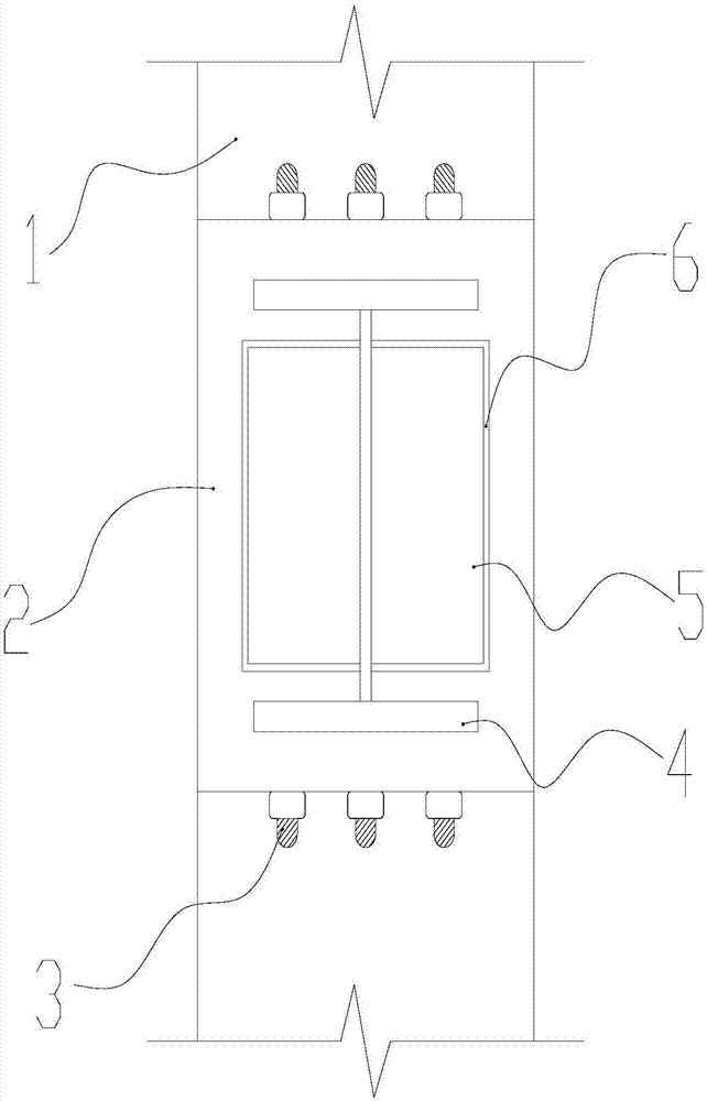
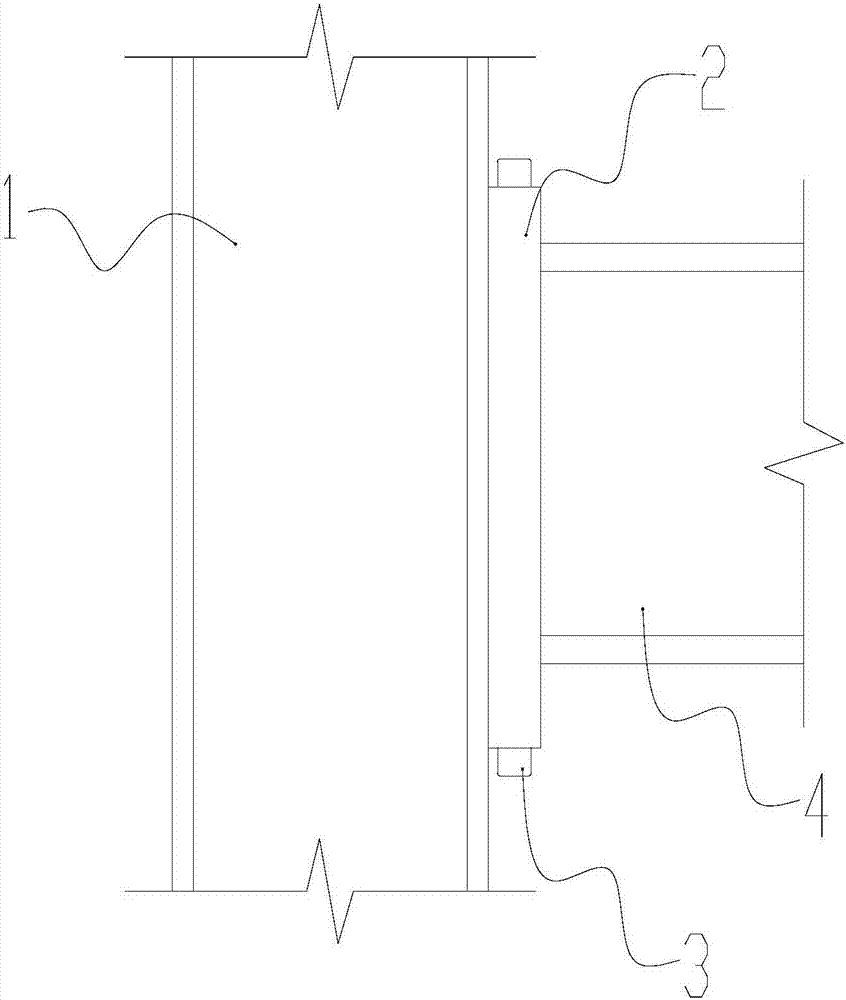
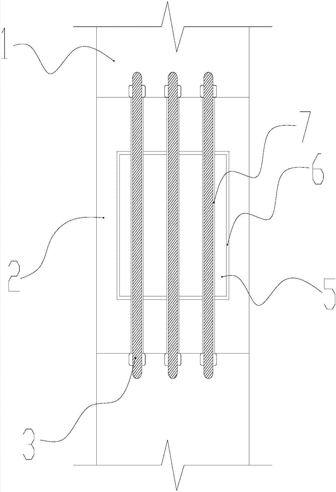
[0016] As shown in the figure, a steel structure node includes a steel structure 1, a nested plate 2, a screw rod 3, a steel structure 2 4, a connecting plate 5, a nested hole 6 and a screw hole 7, and the steel structure 1 is welded with connection Plate 5; a nesting panel 2 is welded on the section steel 2, and a nesting hole 6 is opened in the center of the nesting panel 2; a screw hole 7 is opened on the connecting plate 5 and the nesting panel 2, and the nesting panel 2 passes through the nesting hole 6 It is nested on the connecting plate 5, and the connecting plate 5 and the nesting plate 2 are fixed in the screw hole 7 through the screw rod 3.

[0017] The section steel one 1 can be a steel beam or a steel column, and the section steel two 4 is a steel beam; the connecting plate 5 is fixed on the section steel one 1 by welding, mainly for the ne...


PUM


Abstract

The invention discloses a steel structure node comprising first section steel, a sleeve-embedding plate, screws, second section steel, a connecting plate, a sleeve-embedding hole and screw holes. The steel structure node is characterized in that the connecting plate is welded to the first section steel; the sleeve-embedding plate is welded to the second section steel, and the sleeve-embedding hole is formed in the center of the sleeve-embedding plate; and the screw holes are formed in the connecting plate and the sleeve-embedding plate, the sleeve-embedding plate is arranged on the connecting plate in a sleeve-embedding mode through the sleeve-embedding hole, and the connecting plate and the sleeve-embedding plate are fixed by means of the method that the screws are rotated into the screw holes. Welding on the node all adopts factory welding, and thus danger caused by on-site welding can be effectively avoided. According to the node, the sleeve-embedding plate is arranged on the connecting plate in the sleeve-embedding mode, and the screw holes in the sleeve-embedding plate and the connecting plate are aligned, so that the step that bolt holes are manually and mechanically aligned in air is omitted, and meanwhile danger caused by aloft work can be effectively avoided as well. Through the node, the section steel and the section steel can be conveniently and safely connected together.

Description

technical field [0001] The invention relates to a steel structure node, belonging to the technical field of steel structures. Background technique [0002] In the design, manufacture and installation of existing steel structures, our common joints are welded and bolted connections. Welding is divided into on-site welding and factory welding. In on-site welding, since different buildings have different heights, and most steel structures are high-rise buildings, it is a very dangerous job for welders working at heights, because welding requires The welding time is longer, the sparks are radiating during welding, which is more harmful to the eyes, and the welding precision of the steel structure is relatively high, so there are always reasons why high-altitude welding has become a dangerous and technical work. [0003] Existing bolt connections are divided into rigid joints and hinged joints. Because welding is required for rigid joints, we generally use hinged joints as much ...

Claims


Application Information

Patent Timeline
IPC IPC(8): E04B1/58E04B1/24
CPCE04B1/2403E04B2001/2406E04B2001/2418
Inventor 段玮玮黄柱李强
Owner ZHEJIANG OCEAN UNIV
Learn More