A Multivariable Constraint Control Method for Mounter Drive System Based on Reference Regulator

A driving system and constraint control technology, applied in the direction of control/regulation system, adaptive control, general control system, etc., can solve problems such as damage to the start-up system of the placement machine and the failure of the placement machine to work normally, so as to solve the problem of constraint control. Effect

Active Publication Date: 2020-05-12
HARBIN INST OF TECH
View PDF6 Cites 0 Cited by
  • Summary
  • Abstract
  • Description
  • Claims
  • Application Information

AI Technical Summary

Problems solved by technology

[0003] The purpose of the present invention is to solve the problem of damage to the start-up system of the placement machine due to excessive speed during the movement of the existing placement machine drive system or cause the placement machine to fail because the control input exceeds the maximum input that the placement machine can provide. can not work normally, and propose a multivariable constraint control method for the drive system of the placement machine based on the reference regulator

Method used


Image

  • A Multivariable Constraint Control Method for Mounter Drive System Based on Reference Regulator
  • A Multivariable Constraint Control Method for Mounter Drive System Based on Reference Regulator
  • A Multivariable Constraint Control Method for Mounter Drive System Based on Reference Regulator

Examples


specific Embodiment approach 1

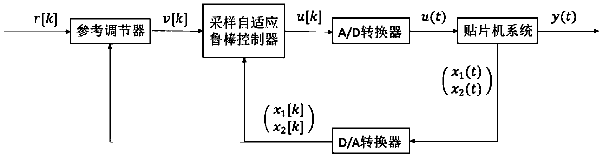
[0021] Embodiment 1: The multivariable constraint control method of the placement machine drive system based on the reference regulator includes the following steps:

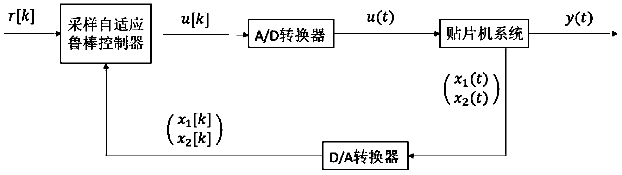
[0022] Step 1. Establish a dynamic model of the drive system of the placement machine moving along the x-axis or the y-axis, express it with a state space model, and determine the constraints imposed on the drive system of the placement machine; the x-axis is horizontal, and the y-axis is vertical;

[0023] Step 2, according to the dynamic model established in step 1, design a sampling controller for the placement machine drive system;

[0024] Step 3. Under the assumption that the unmodeled dynamics of the placement machine drive system and the external disturbance are constant values, predict the state of the placement machine drive system and the size of the control input when the reference signal does not change; the placement machine drive The state of the system includes the displacement and velocity of th...

specific Embodiment approach 2

[0027] Specific embodiment 2: The difference between this embodiment and specific embodiment 1 is that in the step 1, a dynamic model of the drive system of the chip mounter is established along the x-axis or y-axis, represented by a state space model, and the patcher is determined. The specific process of the constraint conditions of the machine-driven system is as follows:

[0028] Ignoring the positioning force and Coulomb friction force when the patch motorized platform moves, according to Newton's second law, establish the dynamic equation when the patch motorized platform moves along the x-axis or y-axis direction, and determine the patch by the method of least squares identification Uncertainty parameters M and B of the machine-driven system, and bounds for external disturbances or unmodeled dynamics:

[0029]

[0030] where M≈11kg∈[θ 1min , θ 1max ]=[10kg,15kg] is the mass of the patch motorized platform, θ 1min and θ 1max are the upper and lower bounds of M, re...

specific Embodiment approach 3

[0036] Specific embodiment three: the difference between this embodiment and specific embodiment one or two is that: in the step two, according to the dynamic model established in step one, the specific process of designing the sampling controller for the drive system of the placement machine is as follows:

[0037] Design an adaptive sampling controller for the system as:

[0038]

[0039] in Denotes kT moment θ 1 the estimated value of Denotes kT moment θ 2 the estimated value of is a virtual sampling control law, the position of the patch maneuvering platform at time kT is x 1 [k], the position error is z 1 [k]=x 1 [k]-r[k], speed is x 2 [k], the speed difference is z 2 [k]=x 2 [k]-α 1 [k], r[k] is the sampling input signal, T is the sampling time, k 1 、k 2 >0 is the controller parameter, is the robust item in the controller, ε is used to adjust and sgn(h[k]·z 2 The parameters of the error size between k), tanh represents the hyperbolic tangent func...


PUM


Abstract

The present invention relates to a multivariable constraint control method of a chip mounter driving system, in particular, a reference regulator-based multivariable constraint control method of a chip mounter driving system. The invention aims to solve problems such as the problem of damage to a chip mounter startup system due to excessively high speed or the problem of the incapability of a chip mounter of working normally due to a condition that control input exceeds maximum input provided by the chip mounter. The method includes the following steps that: (1) the dynamic model of the movement of the chip mounter driving system along an x-axis or a y-axis is built, and constraint conditions imposed on the chip mounter driving system are determined; (2) a sampling controller is designed for the chip mounter driving system; (3) under a condition that the unmodeled dynamic state of the chip mounter driving system and external disturbance are constant, the state of the chip mounter driving system and the magnitude of control input are predicted when reference signals are not changed; and (4) a reference regulator is designed, so that the chip mounter driving system is made to satisfy the constraint conditions in the step (1). The reference regulator-based multivariable constraint control method of the chip mounter driving system of the invention is applied to the multivariable constraint control field.

Description

technical field [0001] The invention relates to the field of multivariable constraint control of the motion system of the mounter, in particular to a multivariable constraint control method of the drive system of the mounter. Background technique [0002] During the working process of the placement machine, according to different needs, the placement motorized platform will be required to meet certain constraints during the movement process. For example, the placement motorized platform must move within a certain range, otherwise it will cause the placement motorized platform Hitting the edge of the placement machine will cause damage to the placement machine equipment; the movement speed of the placement motorized platform cannot reach infinity, or the movement speed of the moving platform cannot be too large due to the limitation of the placement machine's environment; Or, when the placement machine is working, the maximum voltage and current that the placement machine dri...

Claims


Application Information

Patent Timeline
Patent Type & Authority Patents(China)
IPC IPC(8): G05B13/04
CPCG05B13/042
Inventor 刘延斌孙维超高会军
Owner HARBIN INST OF TECH
Why Eureka
Try Eureka