a wire socket

A terminal block and terminal board technology, which is applied in the direction of connection, conductive connection, electrical components, etc., can solve the problems of large occupied area of ​​the terminal block and low wiring efficiency, and achieve the effect of convenient wiring, simple structure and compact overall structure design.

Active Publication Date: 2019-08-27
ZHONGSHAN BROAD OCEAN
View PDF7 Cites 0 Cited by
  • Summary
  • Abstract
  • Description
  • Claims
  • Application Information

AI Technical Summary

Problems solved by technology

[0006] The purpose of the present invention is to provide a terminal block to solve the problems of large occupied area and low wiring efficiency in the prior art

Method used


Image

  • a wire socket
  • a wire socket
  • a wire socket

Examples


Embodiment Construction

[0035] The present invention will be described in further detail below through specific embodiments and in conjunction with the accompanying drawings.

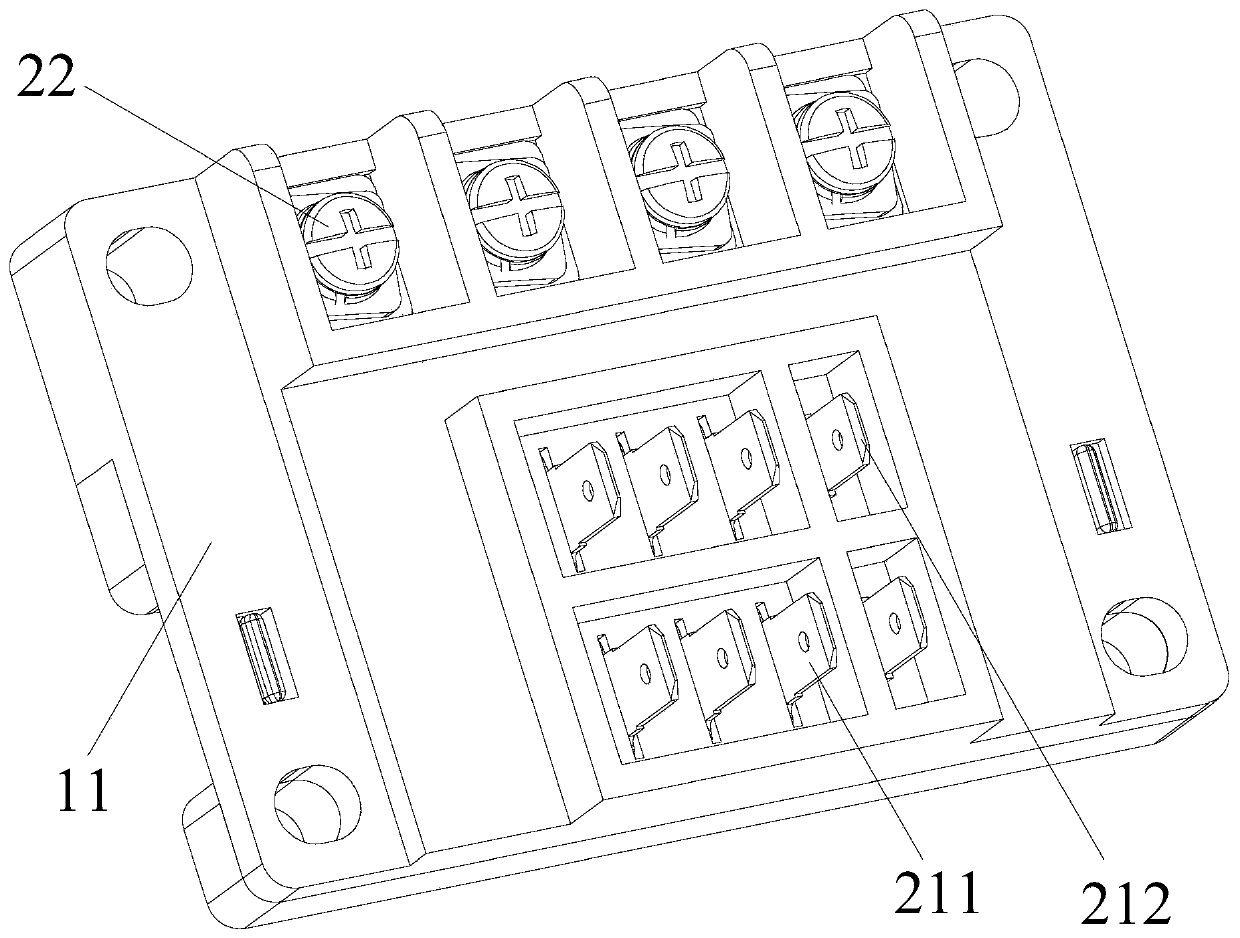
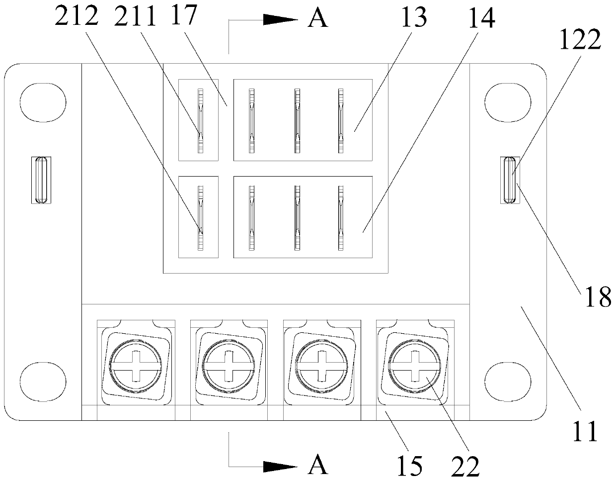
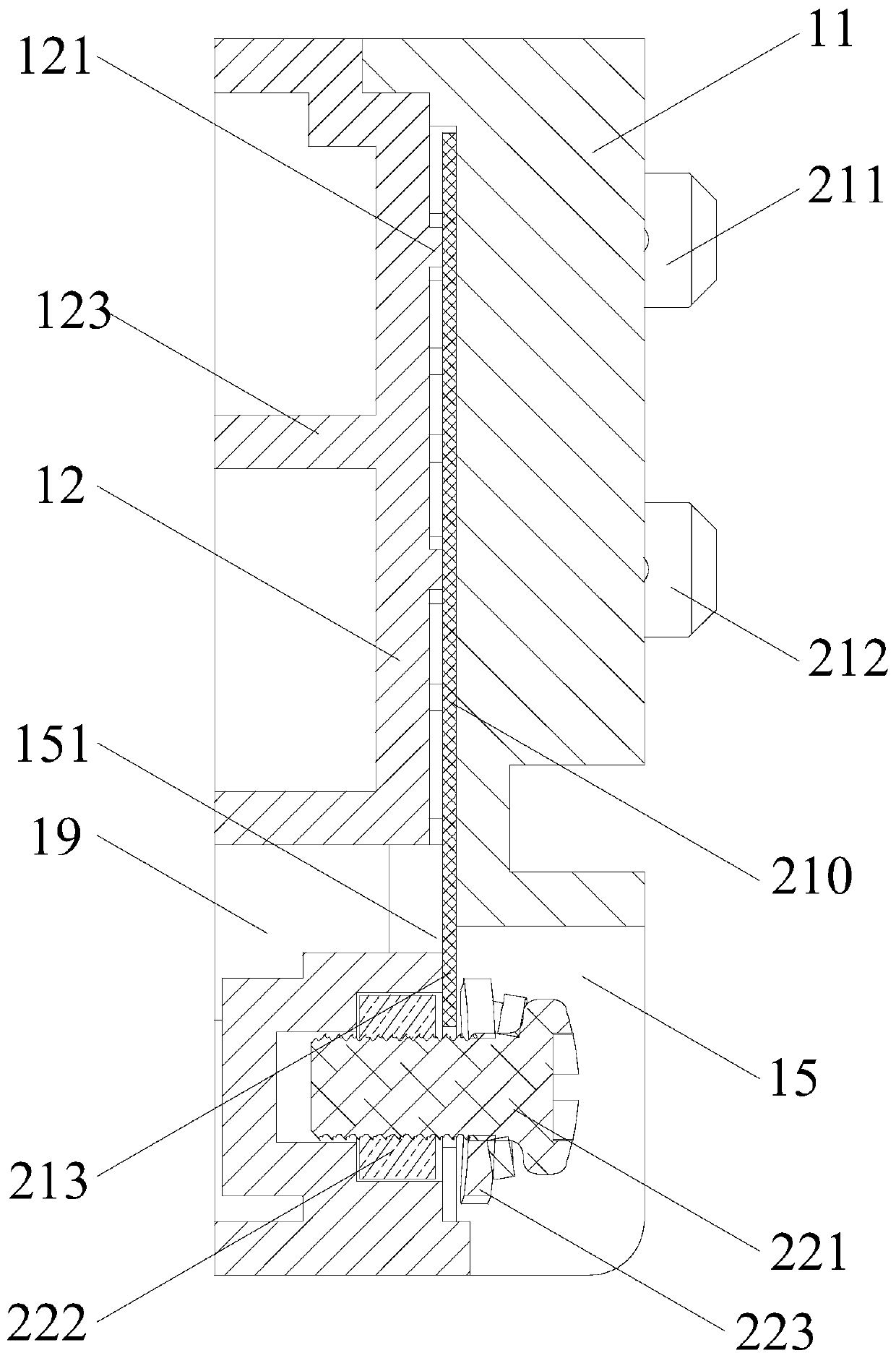
[0036] Such as Figure 1 to Figure 5 As shown, what this embodiment provides is a terminal block, including a terminal board 11, a base plate 12, and several inserts 21 installed between the terminal plate 11 and the base plate 12, wherein the inserts include inserts The chip body 210, the first contact terminal 211, the second contact terminal 212 and the wire pressing piece 213, one end of the insert body 210 protrudes upwards with the first contact terminal 211, and the middle part of the insert body 210 protrudes upwards. The second contact terminal 212, the other end of the blade body 210 is provided with the pressure piece 213, the first contact terminals 211 of several blades 21 are arranged in a row at intervals and protrude from the wiring board 11 above; the second contact terminals 212 of several inserts 21 are arr...


PUM


Abstract

The invention discloses a connector base which includes a wiring board, a bottom board, and a plurality of inserts installed between the wiring board and the bottom board. Each insert includes an insert body, a first contact terminal, a second contact terminal and a wire pressing piece, wherein the first contact terminal protrudes upward from one end of the insert body, the second contact terminal protrudes upward from the middle of the insert body, and the wire pressing piece is arranged at the other end of the insert body. The first contact terminals are arranged at intervals in a row, and protrude from the wiring board. The second contact terminals are arranged at intervals in a row, and protrude from the wiring board. The wire pressing pieces are arranged at intervals and electrically connected with a plurality of wire pressing terminals. The wire pressing terminals are arranged at intervals in a row and installed on the wiring board. The first contact terminals and the second wiring terminals are used for being connected with a motor. The wire pressing terminals are connected with a fan coil load. The connector base is applicable to both a single-machine unit and a double-machine unit. The inserts are simple. The connector base has a compact overall structure.

Description

[0001] Technical field: [0002] The invention relates to a wire socket. [0003] Background technique: [0004] Existing coil fans are generally driven by a motor to work with a load. There is generally a terminal block in the load junction box. The terminal block includes two sets of connecting terminals. The first set of terminals is connected to the motor, and the second set of terminals To connect with the load, each group of terminals has four crimping terminals. But as the load power increases, one motor cannot meet the power demand of the load, so many manufacturers choose two motors to drive the load to work. At this time, two terminal blocks are required in the load terminal box, the first group of terminals of the two terminal blocks are respectively connected to a motor, and the second group of terminals of the two terminal blocks are connected to the load at the same time. In this wiring method, the area occupied by the terminal block is large, which makes the vo...

Claims


Application Information

Patent Timeline
Patent Type & Authority Patents(China)
IPC IPC(8): H01R9/18H01R9/28
Inventor 狄靖昊霍宝福贾洪雨
Owner ZHONGSHAN BROAD OCEAN
Why Eureka
Try Eureka