Electric connector and difference signal set thereof

An electrical connector and differential signal technology, applied in the field of electrical connectors and their differential signal groups, can solve the problems of high-speed electrical connectors, affecting the normal operation of electronic components, affecting the high-frequency transmission performance of electrical connectors and high-speed transmission performance.

Active Publication Date: 2017-10-20
STARCONN ELECTRONICS SU ZHOU CO LTD
View PDF8 Cites 9 Cited by
  • Summary
  • Abstract
  • Description
  • Claims
  • Application Information

AI Technical Summary

Problems solved by technology

Especially with the trend of high-speed transmission of electronic devices, it has led to high-speed electrical connectors
In order to take into account the high-speed requirements of electrical connectors and reduce the high-frequency signal interference that is more likely to occur between the conductive terminals of the electrical connector and the electrical connectors that are plugged into each other, thereby affecting the high-frequency transmission between electrical connectors Performance or high-speed transmission performance, which may affect the normal operation of electronic components (such as mobile phones, laptop computers, tablet computers, desktop computers, digital TVs, etc.) coupled to electrical connectors

Method used


Image

  • Electric connector and difference signal set thereof
  • Electric connector and difference signal set thereof
  • Electric connector and difference signal set thereof

Examples


Embodiment Construction

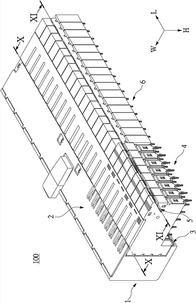
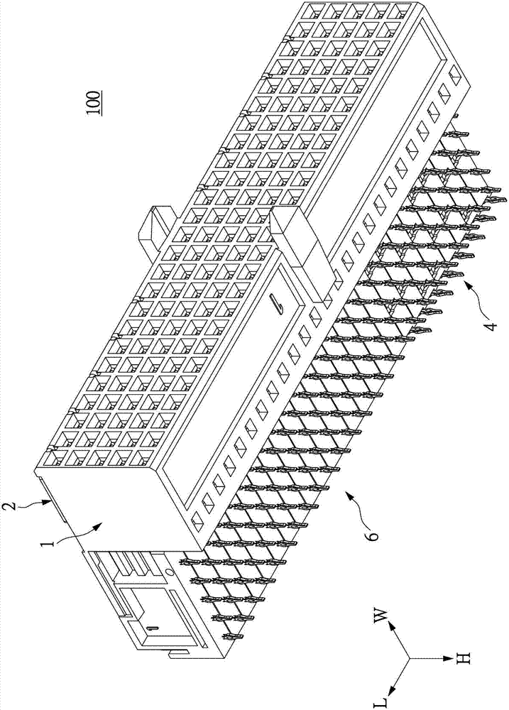
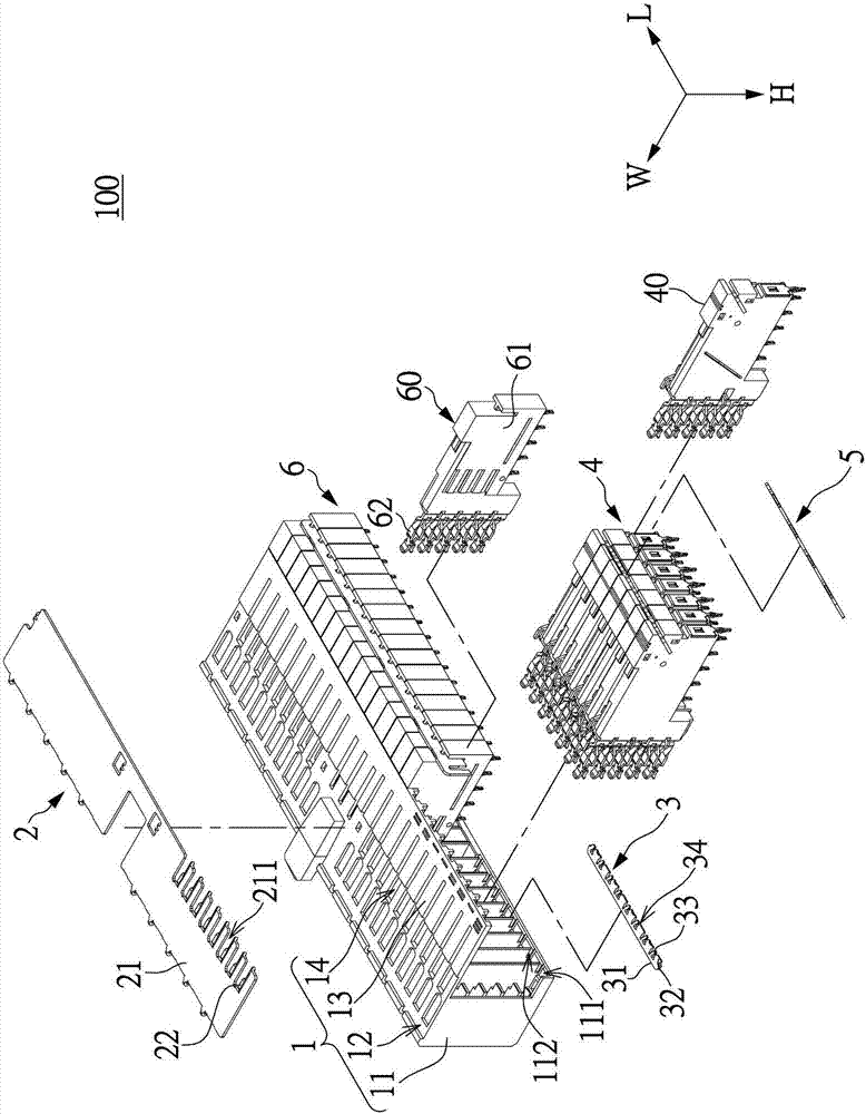
[0033] see Figure 1 to Figure 15 , which is an embodiment of the present invention. What needs to be explained first is that this embodiment corresponds to the relevant quantities and shapes mentioned in the drawings, and is only used to specifically illustrate the implementation of the present invention, so as to facilitate the understanding of the present invention. It is not intended to limit the protection scope of the present invention.

[0034] Such as figure 1 and figure 2 As shown, the present embodiment discloses an electrical connector 100 , especially an electrical connector 100 for transmitting high-frequency (high-speed) signals, but is not limited thereto. The electrical connector 100 includes an insulating housing 1, a shielding sheet 2 installed on the outer surface of the insulating housing 1, a beam 3 installed in the insulating housing 1, and a shielding sheet installed on the insulating housing 1. A differential signal group 4 and a single-ended signal...


PUM


Abstract

An electric connector and a difference signal set thereof. The difference signal set comprises two pairs of difference signal sheets arranged in a row, and any one difference signal sheet comprises a plurality of cooperation portions arranged in a column and a plurality of installation parts arranged in the a column. In the pair of difference signal sheets, each difference signal sheet includes a grounding pin and an offset grounding pin arranged on the two opposite ends adjacent to the column of installation parts, each offset grounding pin and corresponding column of installation parts are arranged in an offset way, the two installation parts on the two ends of each difference signal sheet respectively define two signal installation portions, and the two signal installation portions of each difference signal sheet cooperate respectively with the two signal installation portions of the other difference signal sheet to transmit difference signals. The grounding pins and the offset grounding pins wrap adjacent signal installation portions to reduce external interference and improve high-frequency transmission efficiency.

Description

technical field [0001] The invention relates to a connector, and also relates to an electrical connector and a differential signal group thereof for improving high-frequency anti-interference performance. Background technique [0002] With the development of the computer and related equipment industry, electrical connectors have become an important interface for communication and data transmission between computers and related equipment. In particular, with the trend of high-speed transmission of electronic devices, the high-speed electrical connectors are also brought about. In order to take into account the high-speed requirements of electrical connectors and reduce the high-frequency signal interference that is more likely to occur between the conductive terminals of the electrical connector and the electrical connectors that are plugged into each other, thereby affecting the high-frequency transmission between electrical connectors Performance or high-speed transmission...

Claims


Application Information

Patent Timeline
Patent Type & Authority Applications(China)
IPC IPC(8): H01R13/6461H01R13/648H01R13/6581
CPCH01R13/6461H01R13/648H01R13/6581H01R13/6587H01R13/6471
Inventor 包中南柯宇丰周孙宇王伟
Owner STARCONN ELECTRONICS SU ZHOU CO LTD
Why Eureka
Try Eureka