
Test trolley for vehicle terramechanics soil bin test bed

A technology of ground mechanics and test bench, which is applied in the direction of vehicle trackless test and wheel test, and can solve problems such as difficult road operation, low work efficiency, and low data accuracy

Inactive Publication Date: 2015-10-14
ACADEMY OF ARMORED FORCES ENG PLA
View PDF5 Cites 3 Cited by
  • Summary
  • Abstract
  • Description
  • Claims
  • Application Information

AI Technical Summary

Problems solved by technology

[0002] The optimal design of the vehicle requires a variety of experimental parameters. For example, it is necessary to measure the driving resistance of the wheel under specific soil conditions. However, directly collecting relevant data through the actual running vehicle is not only low in work efficiency, but also requires a large investment. Moreover, it is also difficult to operate all kinds of roads
For this reason, people have designed soil tank test rigs to test the various mechanical properties of wheels, but the test rigs of existing soil tank test rigs can only be tested for wheels with specific structural dimensions. Wheels of different structural sizes need to be manufactured separately, and each soil tank test bench cannot adapt to wheels of various structural sizes, and the existing soil tank test bench is subject to its own power device during the test due to its unreasonable design structure. The interference is large, resulting in low accuracy of the data obtained in the experiment, which will affect the optimal design of the vehicle wheel

Method used


Image

  • Test trolley for vehicle terramechanics soil bin test bed
  • Test trolley for vehicle terramechanics soil bin test bed
  • Test trolley for vehicle terramechanics soil bin test bed

Examples


Embodiment Construction

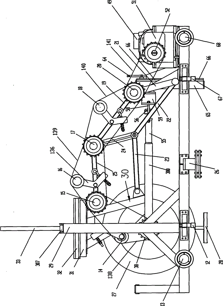
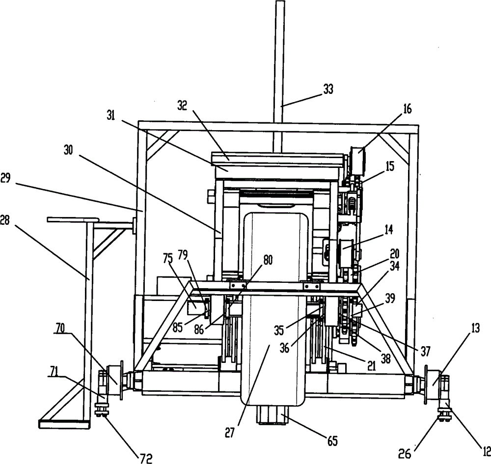
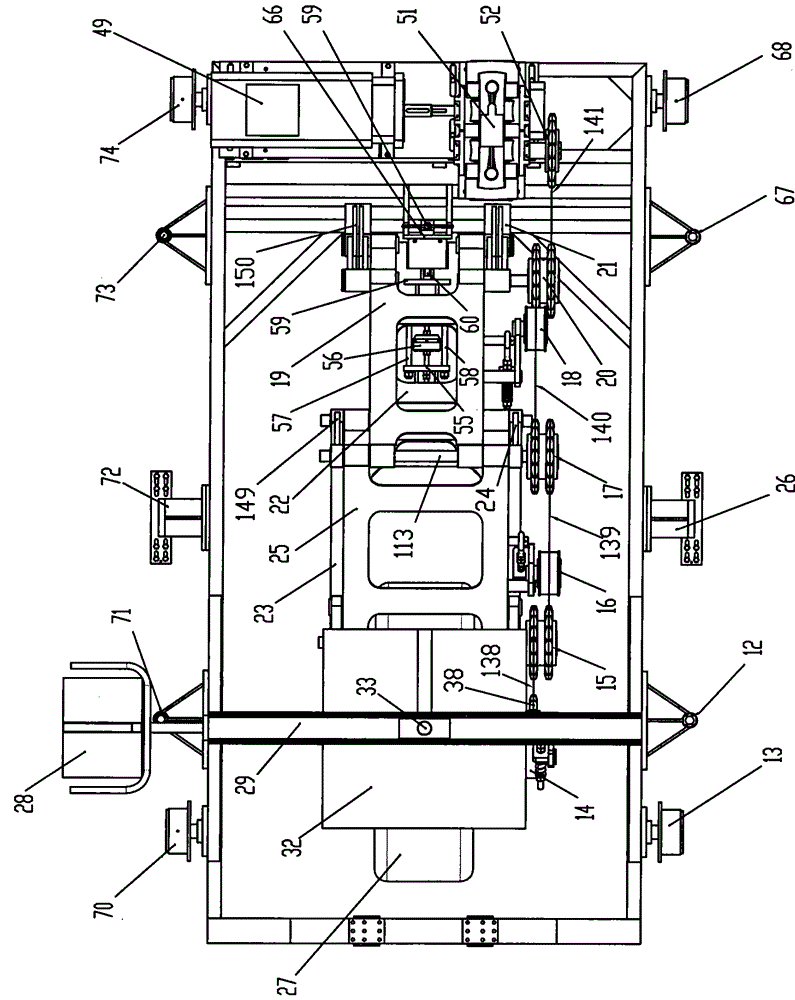
[0048] Such as figure 1 , figure 2 , image 3 , Figure 4 , Figure 5 , Figure 6 with Figure 7 As shown, the vehicle ground mechanics soil tank test bench of the present invention uses a test bench, including a support frame 29, the left end of the bottom front side of the support frame 29 is rotatably provided with a front left support wheel 13, and the support frame 29 bottom front side The right end of the front right support wheel 68 is rotatably provided with, the left end of the support frame 29 bottom rear side is rotatably provided with the rear left support wheel 70, and the right end of the support frame 29 bottom rear side is rotatably provided with the rear right support Wheel 74, the center line of front left support wheel 13, front right support wheel 68, rear left support wheel 70 and rear right support wheel 74 is positioned at front and rear horizontal direction, the bottom of the circumferential surface of rear left support wheel 70 and rear right sup...


PUM


Abstract

The invention discloses a test trolley for a vehicle terramechanics soil bin test bed, which comprises an underframe. The top part of the underframe is fixed with a box body; a front guide rail is arranged at the front end of the top part of the box body along a horizontal direction; a rear guide rail is arranged at the rear end of the top part of the box body along a horizontal direction; the left side of the box body is provided with an electric dynamometer; the base of the electric dynamometer is arranged on the underframe; the rotating shaft of the electric dynamometer is connected with a power input shaft of a power-measuring speed reducer via a coupler; the power output shaft of the power-measuring speed reducer is sleeved with a speed reducer driving sprocket; and the speed reducer driving sprocket is in transmission connected with a speed reducer driven sprocket via a transmission chain. According to the test trolley for the vehicle terramechanics soil bin test bed disclosed by the invention, driving resistance states of wheels of various structural sizes in various soil conditions can be measured, data obtained through the test are precious, various necessary parameters can be provided for vehicle wheel optimization design, and the vehicle wheel performance is optimized.

Description

technical field [0001] The invention relates to a test platform vehicle for a vehicle ground mechanics soil tank test platform. Background technique [0002] The optimal design of the vehicle requires a variety of experimental parameters. For example, it is necessary to measure the driving resistance of the wheel under specific soil conditions. However, directly collecting relevant data through the actual running vehicle is not only low in work efficiency, but also requires a large investment. And it is also difficult to operate all the various roads. For this reason, people have designed soil tank test rigs to test the various mechanical properties of wheels, but the test rigs of existing soil tank test rigs can only be tested for wheels with specific structural dimensions. Wheels of different structural sizes need to be manufactured separately, and each soil tank test bench cannot adapt to wheels of various structural sizes, and the existing soil tank test bench is subjec...

Claims


Application Information

Patent Timeline
IPC IPC(8): G01M17/013G01M17/03
Inventor 李军金嗣淳贾小平于魁龙张甲英刘西侠杨月婷李炯宋海军别尔德别克·吾赞候得崇王丽薇
Owner ACADEMY OF ARMORED FORCES ENG PLA
Learn More