Automatic focusing device with jitter correction structure
An automatic focusing and component technology, applied in color TV parts, TV system parts, TVs, etc., can solve the problems of blurred pictures, small anti-shake compensation angle, and complicated hanging wire structure, so as to improve the stability. Effect
- Summary
- Abstract
- Description
- Claims
- Application Information
AI Technical Summary
Problems solved by technology
Method used
Image
Examples
Embodiment 1
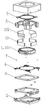
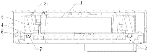
[0035] Such as figure 1 figure 2 The shown autofocus device with shake correction structure includes:
[0036] A lens carrier 1 for carrying a lens;
[0037] a frame 5 for supporting the lens carrier 1;
[0038] Base 2 for supporting lens carrier 1 and frame 5;
[0039] A ball support structure for connecting and supporting the lens carrier 1 or / and the frame 5 with the base;
[0040] The front side spring member 3, which is used to provide restoring force in the optical axis direction, is arranged on the lens carrier and extends in the circumferential direction;
[0041] A rear spring member 4 for providing a restoring force in the direction of the optical axis;
[0042] The elastic angle used to provide XY direction recovery;
[0043] The lens carrier 1 is at least partly arranged in the frame 5 and can be displaced in the frame 5 along the optical axis direction; the lens carrier 1 is surrounded by an electromagnetic drive mechanism for driving the lens carrier 1 to ...
Embodiment 2
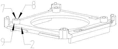
[0050] Such as Figure 4 Figure 5 As shown, there are four rolling support structures below the frame 5, and the frame 5 is displaced on the X and Y planes through the rolling support structures. The rolling support structures include balls 7 and ball mounting holes 8, and the ball mounting holes 8 are arranged on the same plane as On the ball fixing seat 9 integrally connected with the frame 5, the ball 7 is movably installed in the ball mounting hole 8 and the top of the ball 7 protrudes from the lower end surface of the ball mounting hole 8, and the top of the ball 7 is in contact with the supporting surface of the base 2. The frame 5 is displaced on the X and Y planes through the rolling support structure, and the rolling friction can reduce the friction force, improve the vibration correction effect, and increase the response speed.
[0051] Other structures of this embodiment are consistent with Embodiment 1.
PUM
 Abstract
Description
Claims
Application Information
 - R&D Engineer
- R&D Manager
- IP Professional
- Industry Leading Data Capabilities
- Powerful AI technology
- Patent DNA Extraction
Browse by: Latest US Patents, China's latest patents, Technical Efficacy Thesaurus, Application Domain, Technology Topic, Popular Technical Reports.
© 2024 PatSnap. All rights reserved.Legal|Privacy policy|Modern Slavery Act Transparency Statement|Sitemap|About US| Contact US: help@patsnap.com


