Standing-assisted chair with lifting devices
A technology of a transmission device and a chair frame, which is applied in the field of living and home, can solve the problems of a large upturning angle of the seat seat, inconvenient use, easy occurrence of accidents, etc., and achieve the effect of easy standing.
- Summary
- Abstract
- Description
- Claims
- Application Information
AI Technical Summary
Problems solved by technology
Method used
Image

Examples
Embodiment 1
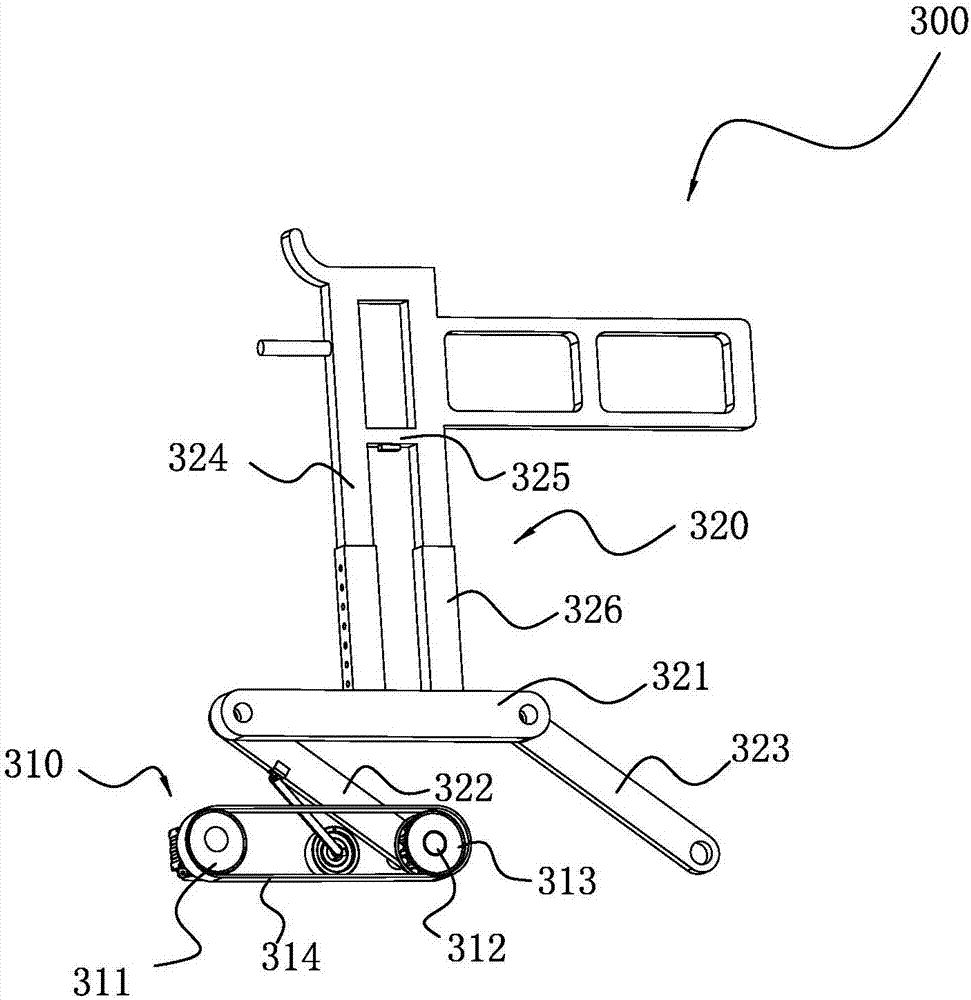
[0030] The lifting device 300 has a belt 314 wheel transmission device 310 and a lifting frame and a backstop 330; the belt 314 wheel transmission device 310 includes a driving wheel 311, a first transmission shaft 312, a driven wheel 313 and a belt 314; The wheel 311 drives the driven wheel 313 through the belt 314, and the driven wheel 313 is sleeved on the first transmission shaft 312, and the first transmission shaft 312 follows the rotation of the driven wheel 313.
[0031] The lifting frame 320 has a first beam 321, a plurality of telescopic rods, a first connecting rod 322 and a second connecting rod 323; connected; the lower end of the first connecting rod 322 is fixedly connected with the first transmission shaft, and the upper end of the second connecting rod 323 is connected with the front end of the first beam 321 through the telescopic rod.
[0032] In this embodiment, before the lifting device 300 is lifted (initial position), the first connecting rod 322 and the...
Embodiment 2
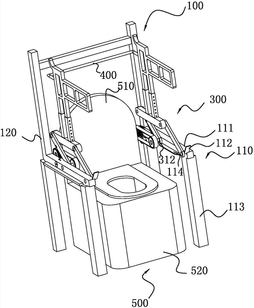
[0041] The auxiliary rising chair with the lifting device 300 includes a chair frame 100 , a motor, a second transmission shaft 200 and the lifting device 300 .
[0042] The chair frame 100 is provided with a chair frame back 120 and two armrests 110 , the armrests 110 have a front leg 113 and a second beam 111 ;
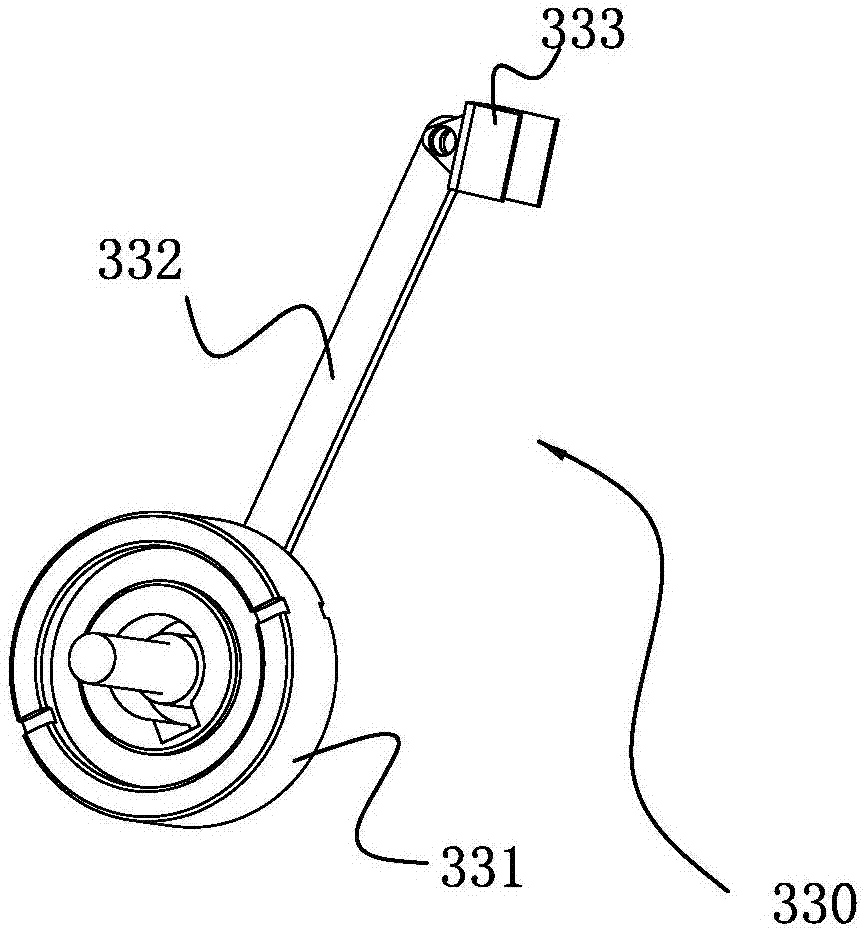
[0043] The two lifting devices 300 are respectively fixed on the two armrests 110, wherein the first transmission shaft 312 is hinged on the second beam 111, and the backstop 330 is fixed on the second beam 111, so The lower end of the second connecting rod 323 is hinged to the front end of the second beam 111 ; the second transmission shaft 200 passes through the two drive wheels 311 in the two lifting devices 300 , and the motor drives the second transmission shaft 200 .
[0044] When the first connecting rod 322 rotates, it also drives the second connecting rod 323 to rotate, and the second connecting rod 323 rotates with the hinge joint with the second beam 111 ...
PUM
 Abstract
Description
Claims
Application Information
 - R&D
- Intellectual Property
- Life Sciences
- Materials
- Tech Scout
- Unparalleled Data Quality
- Higher Quality Content
- 60% Fewer Hallucinations
Browse by: Latest US Patents, China's latest patents, Technical Efficacy Thesaurus, Application Domain, Technology Topic, Popular Technical Reports.
© 2025 PatSnap. All rights reserved.Legal|Privacy policy|Modern Slavery Act Transparency Statement|Sitemap|About US| Contact US: help@patsnap.com