Pinball machine ejection mechanism

A mechanical mechanism and pinball machine technology, applied in indoor games, coin-operated equipment for distributing discrete items, coin-operated equipment with instrument control, etc., can solve problems such as shaking, high maintenance costs, and inaccurate control , to achieve the effect of reasonable structure setting, low maintenance cost and accurate control force

Active Publication Date: 2020-06-02
威海区域创新中心有限责任公司
View PDF3 Cites 0 Cited by
  • Summary
  • Abstract
  • Description
  • Claims
  • Application Information

AI Technical Summary

Problems solved by technology

[0003] 1. Most of the marble ejection mechanism is simply to move the ejector rod downwards and use the counter force of the spring to bounce the marbles. When the ejector rod moves upwards, there may be shaking, instability, etc. Phenomena, making the angle of marble ejection inaccurate and the control force inaccurate;
[0004] 2. The ball ejection mechanical mechanism is usually equipped with a pull rod on one side of the ejector rod. By pulling the pull rod to accumulate elastic force, it is easy to slip off, difficult to control the pulling force and difficult to pull the pull rod in the process of pulling the pull rod, which is inconvenient to use;
[0005] 3. The ejector rod of the marble ejection mechanism is easy to wear between the device and the device when ejecting the marbles, and the service life is short. After the damage, it often needs to be replaced as a whole, and the maintenance cost is high.

Method used


Image

  • Pinball machine ejection mechanism
  • Pinball machine ejection mechanism
  • Pinball machine ejection mechanism

Examples


Embodiment Construction

[0025] The following will clearly and completely describe the technical solutions in the embodiments of the present invention with reference to the accompanying drawings in the embodiments of the present invention. Obviously, the described embodiments are only some, not all, embodiments of the present invention. Based on the embodiments of the present invention, all other embodiments obtained by persons of ordinary skill in the art without making creative efforts belong to the protection scope of the present invention.

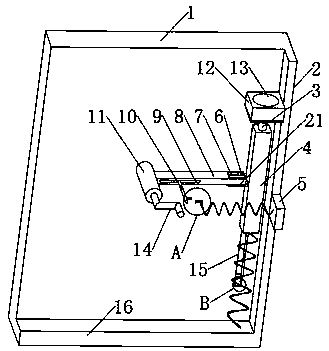
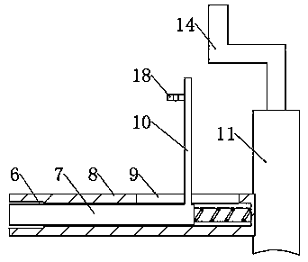
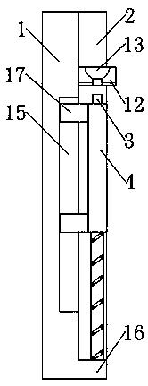
[0026] see Figure 1-6 , the present invention provides a technical solution: a pinball machine ejection mechanical mechanism, including a rotating plate 8, a push rod 4 and a placement plate 12 arranged on a base plate 1, the front end surface on the right side of the base plate 1 is fixedly provided with a right side plate 2, The lower end of the right side plate 2 is fixed with a bottom plate 16, and the bottom plate 16 is fixed on the front end surface bel...


PUM


Abstract

The invention discloses a pop-up ejection mechanism of a pinball machine. The pop-up ejection mechanism comprises a rotary board, an ejection rod and a placing board, all of which are arranged on a base board. The front end surface of the right side of the base board is provided with a right side board. The lower end of the right side board is fixedly provided with a bottom board. The bottom board is arranged below the front end surface of the base board. The middle position at the front end of the base board is movably provided with a rotary shaft. The front end of the rotary shaft is fixedly provided with a handle. Elevating rods at one end of the ejection rod are arranged in a force accumulation groove. When moving upward, the ejection rod does not shake and keeps stable such that a hoodle has an accurate pop-up ejection angle and accurate control force. The inner walls at upper and lower ends of the lower surface of the placing board and the force accumulation groove are provided with buffer boards. When the ejection rod moves up and down, damage to parts in the mechanism is not easily caused. The abrasion of the ejection rod is little, thereby prolonging the service lifetime of the ejection rod. When damage is caused, the buffer boards are only needed replacing so that there is no need to integrally replace the mechanism. The pop-up ejection mechanism of the pinball machine is low in maintenance cost and suitable for promotion.

Description

technical field [0001] The invention relates to the technical field of mechanical structures, in particular to a pinball machine ejection mechanical mechanism. Background technique [0002] The pinball machine was invented in Nagoya City in the early 20th century. It originated from the coin-operated game machine with prizes in the Taisho era. It is a game machine for children to play. The core structure of the pinball machine is its internal pinball ejection mechanism. At present, many mechanical structures also refer to the marble ejection mechanism to achieve specific functions, but this kind of marble ejection mechanism still has the following disadvantages in actual use: [0003] 1. Most of the marble ejection mechanism is simply to move the ejector rod downwards and use the counter force of the spring to bounce the marbles. When the ejector rod moves upwards, there may be shaking, instability, etc. Phenomena, making the angle of marble ejection inaccurate and the cont...

Claims


Application Information

Patent Timeline
Patent Type & Authority Patents(China)
IPC IPC(8): A63F9/02A63F7/04G07F17/38
CPCA63F7/04A63F9/02G07F17/38
Inventor 周涛
Owner 威海区域创新中心有限责任公司
Why Eureka
Try Eureka