
Dusting machine

A technology for dust collectors and casings, which is applied in the direction of dispersed particle filtration, membrane filters, membrane technology, etc., and can solve the problems of unsealed casings and dust flying out, etc.

Inactive Publication Date: 2017-10-24
JIANGYIN BAISHUN TECH
View PDF0 Cites 1 Cited by
  • Summary
  • Abstract
  • Description
  • Claims
  • Application Information

AI Technical Summary

Problems solved by technology

However, there is another problem at the same time. In the process of driving the filter bag to vibrate, the cleaning device may cause the casing to be leaky, so that the dust will fly out of the casing from the gap.

Method used


Image

  • Dusting machine
  • Dusting machine

Examples


Embodiment 1

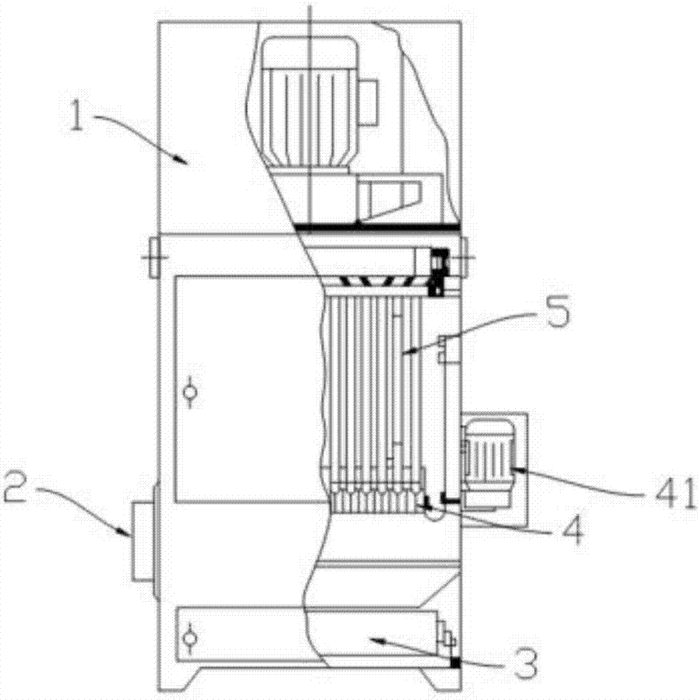
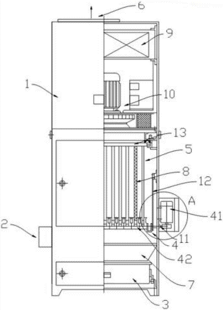
[0015] see figure 1 , 2 As shown, a dust remover includes a casing 1, a dust removal component, an ash collecting tank 3, and a dust removal device 4. The casing 1 is the main structure of the dust collector, and the casing 1 is generally in the shape of a cuboid, which is placed on the ground. In this embodiment, an air inlet 2 is opened at the bottom of the casing 1 , and an air outlet 6 is opened at the top of the casing 1 . The dusty gas enters the casing 1 from the air inlet 2 and leaves the casing 1 through the air outlet 6 . The dust removal part is located in the casing 1 . After the dust-containing gas passes through the dust-removing component, the dust in the dust-containing gas is retained in the casing 1 , and the clean gas is led out of the casing 1 through the air outlet 6 . The dust removal components include a frame 13 and a filter bag 5 . The frame 13 is detachably arranged on the casing 1 and connected to the inner wall of the casing 1 . The frame 13 i...


PUM


Abstract

The invention discloses a dusting machine which comprises a shell, a dusting component, a dust collection groove and a dust cleaning device. An air inlet and an air outlet are formed in the shell, the dusting component is positioned in the shell and comprises a frame and a filter bag, the frame is arranged on the shell, the filter bag sleeve the frame, the dust collection groove is positioned below the filter bag, the dust cleaning device comprises a connecting portion, a motor and a sealing part, the connecting portion is arranged on the filter bag, the motor is used for driving the connecting portion to motion, the sealing part is positioned outside the shell and has elasticity, the connecting portion is provided with one end, the end penetrates the shell and is lined with an output wheel of the motor, one end of the sealing part is fixedly connected with the shell, and the other end of the sealing part sleeves the one of the connecting portion penetrating the shell. By the aid of the structure, the dusting machine can achieve closeness of the shell in the vibrating and dust cleaning process, and dust can be easily discharged from the shell.

Description

technical field [0001] The invention belongs to a dust removal device, in particular to a dust remover. Background technique [0002] In the prior art, the dust-laden gas enters the casing from the air inlet, and after being filtered by the filter bag and the filter screen, the dust is retained on the outer surface of the filter bag, and the filtered gas is discharged from the air outlet through the filter bag. shell. As the filtration time increases, the dust attached to the outer surface of the filter bag will also increase, and the resistance of the filter bag will also increase accordingly, thus affecting the suction and dust removal effect. Such as figure 1 As shown, at this time, the dust cleaning device is required to vibrate the filter bag to shake off the dust on the outer surface of the filter bag. However, there is another problem at the same time. During the process of driving the filter bag to vibrate, the cleaning device may cause the casing to not be sealed...

Claims


Application Information

Patent Timeline
Patent Type & Authority Applications(China)
IPC IPC(8): B01D46/02B01D46/04B01D46/48
CPCB01D46/023B01D46/04B01D46/48B01D2267/30B01D2267/70B01D2271/02B01D46/76
Inventor 单绍超陈建忠顾志宏
Owner JIANGYIN BAISHUN TECH
Learn More