
Cutting device

A technology of cutting device and cutting equipment, which is applied in the field of metal cutting, and can solve the problems of unguaranteed quality of metal shell, low cutting precision, and easy miscutting of product segments, etc.

Inactive Publication Date: 2017-10-24
HUBEI SANJIANG AEROSPACE GRP HONGYANG ELECTROMECHANICAL
View PDF1 Cites 2 Cited by
  • Summary
  • Abstract
  • Description
  • Claims
  • Application Information

AI Technical Summary

Problems solved by technology

[0005] Aiming at the problems existing in the prior art, the embodiment of the present invention provides a cutting device, which is used to solve the problem of low cutting precision and easy mistakes in the prior art when manual cutting is used to cut the redundant heat-proof layer on the metal shell. Cutting the product segment, which leads to the technical problem that the quality of the metal shell cannot be guaranteed

Method used


Image

  • Cutting device
  • Cutting device
  • Cutting device

Examples


Embodiment Construction

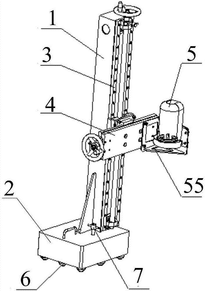
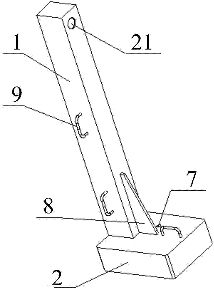
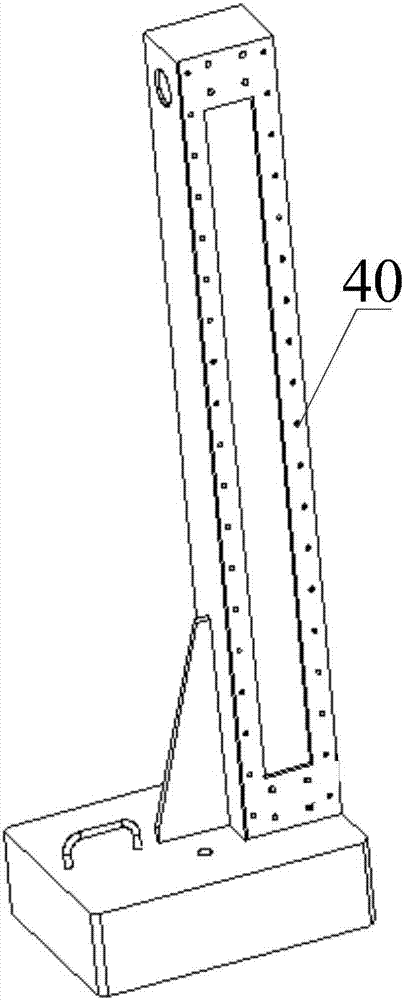
[0056] In order to solve the technical problems in the prior art that when the redundant heat-proof layer on the metal shell is cut by manual cutting, the cutting precision is low, and the product section is easily cut by mistake, which leads to the unguaranteed quality of the metal shell. The invention provides a cutting device, which comprises: a first pillar, one end of the first pillar is connected with one end of the base, and a vertical movement mechanism is installed on one side of the first pillar; the vertical movement mechanism Used to adjust the position of the cutting device in the vertical direction; a horizontal movement mechanism, the horizontal movement mechanism is connected to the vertical movement mechanism through a drive plate; the horizontal movement mechanism is used to adjust the position of the cutting device in the horizontal direction; Cutting equipment, the cutting equipment is connected to one end of the horizontal movement mechanism through the sec...


PUM


Abstract

The invention provides a cutting device. According to the device, one end of a first supporting pillar is connected with one end of a base, and one side of the first supporting pillar is further provided with a perpendicular moving mechanism; the perpendicular moving mechanism is used for adjusting the position, in the vertical direction, of the cutting device; a horizontal moving mechanism is connected with the perpendicular moving mechanism through a driving plate; the horizontal moving mechanism is used for adjusting the position, in the horizontal direction, of the cutting device; the cutting device is connected with the horizontal moving mechanism through a second supporting pillar; a walking part is installed at the other end of the base; and thus, the position, in the vertical direction, of the cutting device can be adjusted according to the perpendicular moving mechanism, the position, in the horizontal direction, of the cutting device can be adjusted through the horizontal moving mechanism, the cutting device can accurately reach the cutting position, and the cutting precision is improved.

Description

technical field [0001] The invention belongs to the technical field of metal cutting, and in particular relates to a cutting device. Background technique [0002] The outer surface of the metal shell needs to be covered with a layer of glass fiber reinforced plastic heat-proof layer in special use environments to ensure the use effect of the metal shell. [0003] Shell FRP winding molding is a relatively common method for forming the heat-resistant layer of the shell. On the winding machine, the FRP cloth tape or FRP wire is directly wound on the outer surface of the metal shell, and then enters the oven or autoclave for high-temperature curing molding. In order to ensure the quality of FRP winding near the front and rear end surfaces of the shell, it is generally necessary to use the front extension section and the rear extension section to extend the metal shell forward and backward respectively, so that the FRP starts to wind from the front extension section. , and then ...

Claims


Application Information

Patent Timeline
IPC IPC(8): B29C53/80
CPCB29C53/8091
Inventor 吕建刚张文明金达海邹一飞
Owner HUBEI SANJIANG AEROSPACE GRP HONGYANG ELECTROMECHANICAL
Learn More