
Check valve

A technology of check valves and valve sleeves, which is applied in the direction of lifting valves, control valves, valve devices, etc., can solve the problems of high labor intensity, inconvenient maintenance, and complicated installation, and achieve the effect of reducing labor intensity and convenient maintenance

Active Publication Date: 2017-10-24
WILO CHINA
View PDF5 Cites 3 Cited by
  • Summary
  • Abstract
  • Description
  • Claims
  • Application Information

AI Technical Summary

Problems solved by technology

[0003] The purpose of the present invention is to provide a check valve. Through this technical solution, not only can the complex installation, poor sealing performance and easy water leakage after assembly be solved in the production process, but also practical problems such as inconvenient maintenance and high labor intensity can be solved.

Method used


Image

  • Check valve
  • Check valve
  • Check valve

Examples


Embodiment Construction

[0030] The technical solutions of the present invention will be described in further detail below with reference to the accompanying drawings and embodiments.

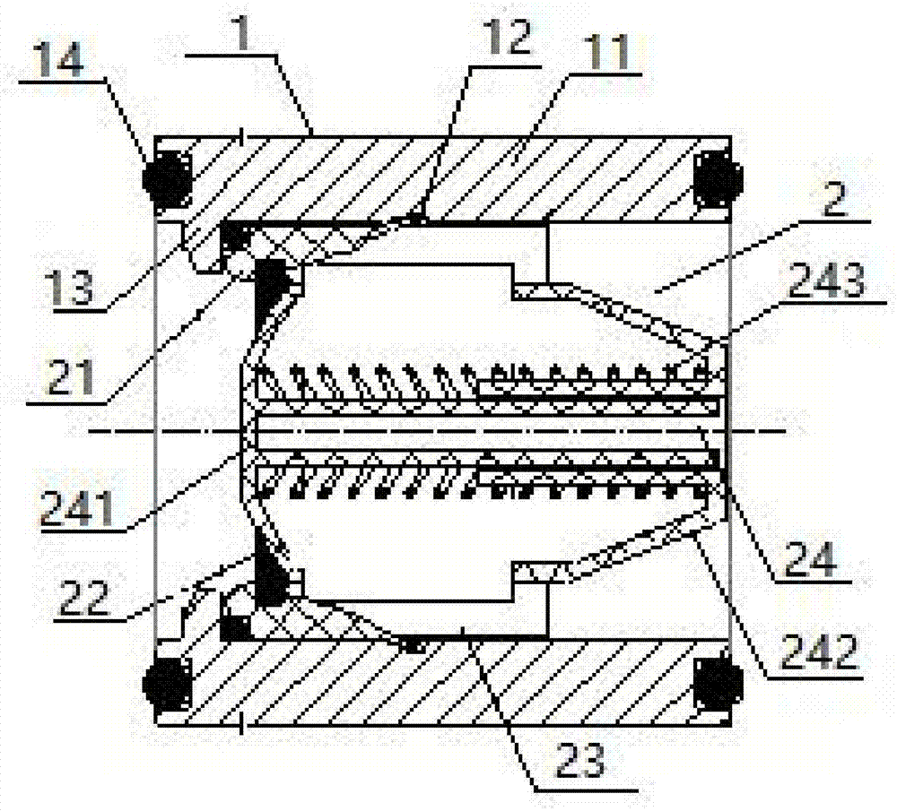
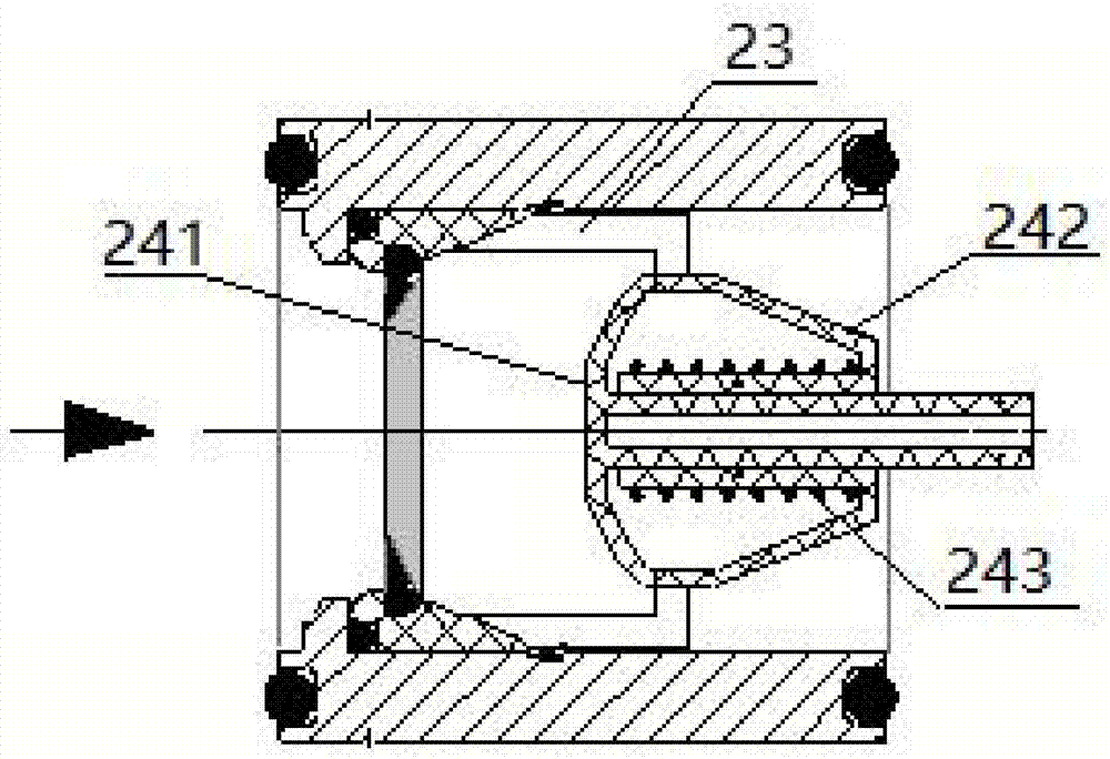
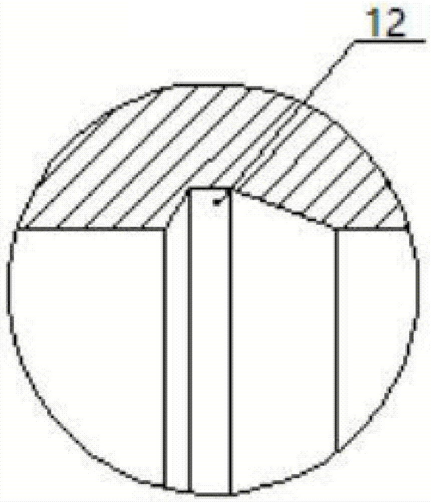
[0031] The check valve provided by the embodiment of the present invention includes a valve sleeve 1 and a valve body 2, the valve sleeve 1 includes a valve sleeve slot 12, the valve body 2 includes a valve body sleeve 23, and the buckle on the valve body sleeve 23 and the valve sleeve The clamping grooves 12 are connected to clamp the valve body 2 on the valve sleeve 1 . The valve body 2 also includes a spool 24, and the spool 24 includes a first connecting portion 241, a second connecting portion 242 and a spring 243, and the first connecting rod of the first connecting portion 241 is inserted into the second connecting portion 242. In the connecting rod, the spring 243 is sleeved on the second connecting rod. When water flows in, pressure is applied to the first connecting portion 241 to open the water inlet, and w...


PUM


Abstract

The embodiment of the invention relates to a check valve. The check valve comprises a valve sleeve and a valve body. The valve sleeve comprises a valve sleeve body, a valve sleeve clamping groove, a limiting ring, valve sleeve sealing grooves and first sealing rings, wherein the valve sleeve clamping groove is formed in the inner side wall of the valve sleeve body, the limiting ring is located on the inner side wall of the portion in front of the valve sleeve clamping groove, the valve sleeve sealing grooves are formed in the two ends of the valve sleeve, and the first sealing rings are held in the valve sleeve sealing grooves. The valve body comprises a locating ring, a second sealing ring, a blocking piece, valve body clamping sleeves and a valve element. The locating ring abuts against the inner side of the limiting ring, a first groove is formed in the top of the locating ring, and a second groove is formed in the inner side of the locating ring. The second sealing ring is held in the first groove of the locating ring. The blocking piece comprises a through hole and is inserted into the second groove in a connected mode. The valve body clamping sleeves are located on the inner side of the blocking piece and abut against buckle rings on the outer side walls of the valve body clamping sleeves. The valve element comprises a first connecting portion, a second connecting portion and a spring. The first connecting portion comprises an abutting portion and a first connecting rod, wherein the abutting portion abuts against the through hole of the blocking piece. The second connecting portion comprises a fixing rod and a second connecting rod, wherein the fixing rod and the second connecting rod are connected with each other, the fixing rod and the valve body clamping sleeves are fixed, and the second connecting rod sleeves the first connecting rod in a connected mode. The spring sleeves the outer side of the second connecting rod in a connected mode.

Description

technical field [0001] The invention relates to the field of water supply equipment, in particular to a check valve. Background technique [0002] At present, in the check valve installed at the outlet of the elliptical flange pump, the technology used is the check valve connected by the internal thread thread, and the front and rear connections need to add various fittings such as wires and unions. In order to achieve the sealing purpose of the threaded connection, it is necessary to process and manufacture a special sealing tapered pipe thread, and at the same time, it is necessary to wind the hemp rope and the raw material tape on the thread. There are still many problems and deficiencies in the above products, especially in the processing of tapered pipe threads. If the processing accuracy is not up to standard, it will easily cause poor sealing effect, difficult installation and water leakage. For water supply equipment composed of multiple pumps, if a check valve is d...

Claims


Application Information

Patent Timeline
IPC IPC(8): F16K15/06F16K1/32
CPCF16K1/32F16K15/063
Inventor 朱建阳李平洲滕人博鲍慧梅
Owner WILO CHINA
Learn More